Mic Pre Amps/ Phantom power/ Phase reverse switches
The channel Input on a professional mixing console can accept either a microphone or line- level source, and each microphone input includes a switchable +48 volt phantom power switch for condenser microphones. The input is electronically balanced but can accept an optional balancing transformer.
The microphone preamplifier sensitivity or gain control knob, in conjunction with the “-20Db Pad” switch, adjusts the preamp gain to accommodate low- level sources like footlight microphones, mid- level sources like handheld performer microphones or high- level sources like electronic musical instruments.

Venue channel input page
Each input includes a polarity inversion switch (“Phase”) to correct miswired microphone cables or microphones with reverse polarity, and a switchable or fully adjustable “high- pass” filter knob or switch to reduce the popping sound from a performer’s voice or other low frequency noises.

Analog console overview
The signal flow through an analog console is very easy to follow. A microphone signal enters at one of the channel inputs and is amplified by the microphone preamplifier. The operator adjusts the level of the microphone with the input volume control. The microphones are “mixed” into the stereo mix busses, and the combined signals proceed through the mix amplifiers and master volume control to the mixer’s output.
While this simple mixer is adequate for some applications, many systems need the additional features found in a more sophisticated mixing console like the one shown in Figure 1-2 and 1-3.
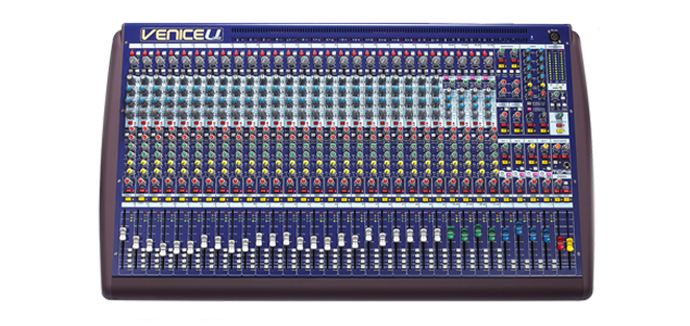
Figure 1-2 Midas Venice 24ch. analog mixing console
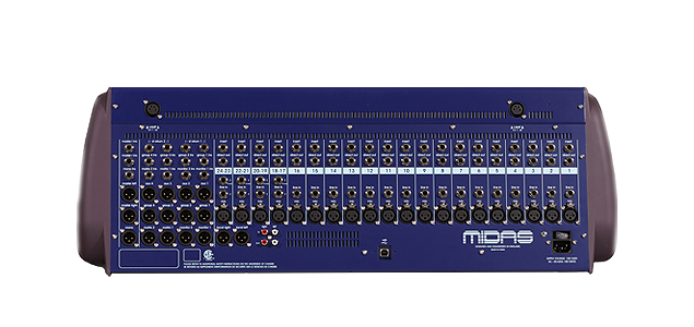
Figure 1-3 Midas Venice 24ch. analog mixing console rear
This mixing console has additional input features including 4- band parametric equalization (tone control), input sensitivity and -20Db pad adjustments.
Each input can accept either a microphone or line-level source, and that each microphone input includes switchable + 48 volt phantom power for condenser microphones, phase reverse and a variable high pass filter.
Each channel can feed multiple mix buses including a stereo mix output, channel direct output, aux. outputs and matrix mix outputs.
Console Metering
Smaller or low-cost mixing consoles may have minimal metering. Mid-sized and large mixing consoles may have optional metering in the form of a meter bridge located above the back of the console and individual channel metering located beside the fader. Each input channel will also have a peak LED (sometimes called a clip LED). This feature helps the operator set the input sensitivity control and watch for excessive input level. Some mixing consoles also include a signal present LED to show when a low-level signal is present in the input channel. This feature helps the operator know if a microphone is actually working. LED bar -graph meters or analog VU meters are more important on group and output channels. Here , they help the operator balance the levels in each group or output and avoid excessive average level. Commonly, group and output channels will also include peak LEDs and may also include signal present LEDs.
![]()
Digital console overview
Digital mixing consoles share many of the same performance specifications with analog mixing consoles. However, digital products in general also have a whole new set of performance specifications.
Figure 1-1 shows the performance specifications for a digital mixing console. Included in this chart are specifications for sampling frequency and throughput signal delay. This mixing console’s sampling frequency is the same as a standard CD (44.1 kHz) or DAT recorder (44.1 or 48 kHz). Its signal delay of 2.5 msec represents the time a signal takes to enter at an input, pass through the digital processing circuits and exit at an output. (This specification may also be called latency.)

Performance specifications are measured under controlled, laboratory conditions. Performance in real-world conditions may be different. For example, a mixing console used outdoors in temperature extremes may not meet its published performance specifications. A mixing console with poor internal grounding design may not meet its published noise specifications when operated in a facility with noisy AC circuits.
The digital consoles metering is also different from it’s analog counterpart, it uses “DBFS” (Decibels relative to full scale) metering as opposed to the analog style Vu (Volume unit) scale.
Typically a -20dB FS 1kHz test signal is equal to 0dB VU. And 0dB VU is equal to +4dBu (the”U” stands for unspecified & undetermined) / 1.23 Volts RMS – using a true RMS volt meter.
The other factors on how well a digital console sounds and performs are the following:
Sampling frequency rate-(Sample rate is the number of samples per second, measured in hertz (Hz) or kilohertz (kHz). A rate of 44,100 samples per second is more commonly referred to as 44.1 kHz.)
Bit depth-(In digital audio using pulse-code modulation (PCM), bit depth is the number of bits of information in each sample, and it directly corresponds to the resolution of each sample.(Examples of bit depth include Compact Disc Digital Audio, which uses 16 bits per sample, and DVD-Audio and Blu-ray Disc which can support up to 24 bits per sample.)
Console internal features, such as internal to external routing, onboard compressors, noise gates, equalizers and effects processors.
Setting up and connecting the Avid D-Show console
Digital console set up and connections must be done per the manufacturers specifications and guidelines to ensure optimal operating performance.
We’ll use the Avid D-Show console for an example:

Avid D-Show console system
“Components List”
* D-Show console main surface
* D-Show console side car surface
* FOH computer rack
* Stage rack (48ch. x 24-outputs)
* Video monitor
* FOH console link cable (not shown)
* 110 Ohm digital XLR console interconnect cable (not shown)
* BNC digital console snake (not shown)
* Eazy tilt console stand
The location and connections of these pieces are as follows:
1. D-Show console main and side car surfaces are connected together via a special 110 ohm XLR cable,the
console sits on the “Eazy tilt” stand and it is either located at front of house mix position (FOH) or at the monitor mix position.
2. FOH computer rack is located with the console and is connected via the “console Link” cable.
3. The “Video monitor” is connected to the VGA connector on the rear of the main console surface
4. The “Stage rack” is either located at FOH position if the console is to be used as a front of house mix console, and is connected to the “FOH computer” rack via the 30ft. “BNC” digital snake.
(The stage rack could also be located at the monitor mix position as a more convenient position to the stage instruments and connected via a 300ft. BNC digital snake)
The correct power up & shut down procedure is as follows:
1st.- Power on the stage rack(s)
2nd – Power on the console suface(s)
3rd – Power on the FOH computer rack
4th – Go to options tab/system (select shut down)
![]()
Gain structure, setting channel input levels to unity gain!
Getting the correct input level on a vocal mic or instrument is the most important part of operating the mixing console.
This can be accomplished by a technique called unity gain. There are several stages in a mixer where the signal can be amplified: at the mic preamp, at the channel fader, and where the channels are grouped together in the master section. At each of these areas gain must be maximized in order to obtain a good signal to noise ratio and to prevent distortion.
To compensate for the wide range of signal levels, many mixers have a TRIM or PAD control which allows a proper amount of signal to be sent to the pre-amp. If a strong signal source is used on a mixer without some type of TRIM or PAD control, distortion could occur. If a weak source was used, the mixer would require so much added gain that noise or hiss would develop.
Depending on the mixer, this function is achieved by variable attenuators or slide switches. A variable attenuator or (mic preamp) as its most commonly called allows more precise setting, thereby increasing the signal to noise ratio.
If the input stage is over-driven, distortion will occur. Sometimes it may be difficult to determine exactly which input is distorting when many signal sources are being used. The peak LED indicator eliminates the guesswork. It illuminates when the input is approaching the clipping or distortion level. Occasional blinking is permitted, but if a more steady light occurs, the TRIM or -20Db PAD for that channel should be readjusted to reduce the level.
Obtaining the correct input gain:
The fader which determines the level or volume for each channel usually does not add gain, but merely reduces the level that is there. This volume control should not be turned up all the way for starters,
It should be set at a level where the operator can boost or cut volume during the performance. On many mixers this nominal operating area is designated by “0 dB” or some graphic element indicating a normal operating level. If the mixer is not labeled as such, turn the volume control halfway up. This will allow boosting or cutting as needed.
On all professional consoles each input channel has a “PFL” (Pre fade listen) or “CUE” button, which feeds an isolated bus that has an associated LED or VU meter that is usually located in the master section of the console.
The “PFL” or soloed signal can be heard on the headphone system of the console also.
The operator uses the “PFL” function to solo the in coming audio signal and properly set the microphone preamp level by raising or lowering the variable attenuator knob (mic preamp) and or switching in or out the “-20Db PAD” switch.
The proper input meter level the operator should try to achieve is varied based on the source of the audio signal and the type of metering that’s in use on the console. (Some consoles have switchable input/output metering on each input channel strip)
Example input levels for Vu style metering:

- Analog Vu meter
Kick Drum= 0Db
Snare Drum= 0Db
Vocal Mics= 0Db
Hi Hats= -7Db
Bass Gtr.= -7Db
Special Note:
These reference levels are arbitrary and should be used as a guide, all brands of mixing consoles yield different outputs based on the input signal level
![]()
Console output levels
After a good channel input level has been achieved and routed thru all of the dynamics (Eq.,Compressors,Noise Gates,Etc..) processing needed to tailor the sound to the operators liking, and with the fader setting at the 0Db “Unity gain” mark on the fader panel, The signal is then bussed to the stereo mix fader via the channel pan pot for it’s final output to the speaker system processing.
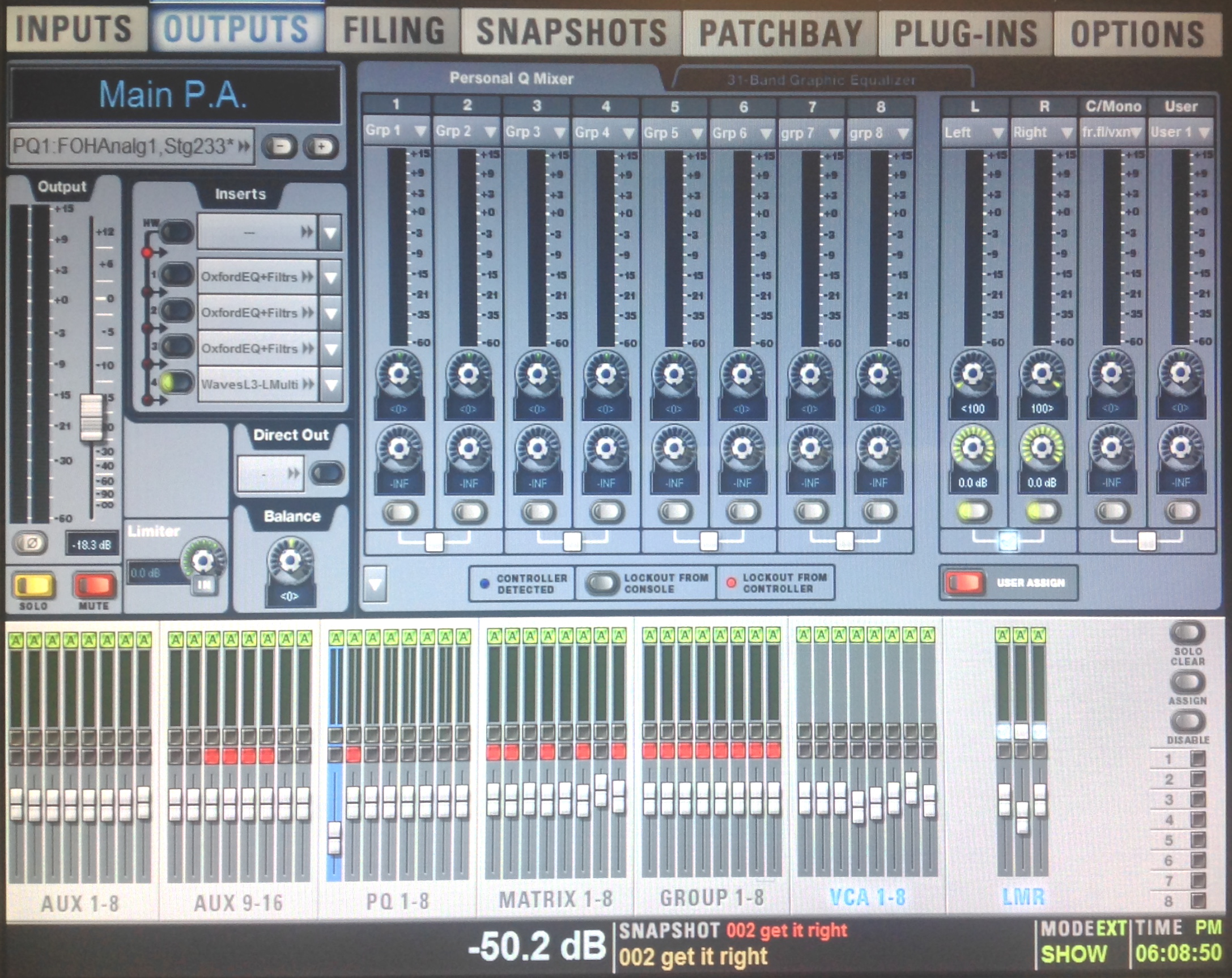
Venue Ouput page
The theory behind “Unity Gain” is that, when the mic preamp level is adjusted to make the source input signal peak out at “0Db” on the PFL meter or channel input meter, the channel fader can then be set at the 0Db or “nominal” operating level denoted on the fader panel.
This will intern send a 0Db output from the channel fader to the stereo bus fader which will cause a 0Db output reading on the master stereo Vu or LED console meters.
0Db input equals 0Db output and yields the best signal to noise ratio the console can deliver.
Special Note:
All consoles are “NOT” calibrated to 0Db!!
![]()
Digital distortion and audio clipping- in progress…
Distortion could occur when either the mic preamp level, Equalizer levels or the Internal/ external signal processor levels are not maintained at unity gain.
![]()
![]()
What is Sound ?
For our purposes we will define sound as fluctuations, or variations, in air pressure over the audible range of human hearing. This is normally taken as the frequency range from about 20 cycles per second up to about 20,000 cycles per second. The term hertz (abbreviated Hz) is universally used to indicate cycles per second. Likewise, the term kilohertz (kHz) indicates one-thousand Hz. We can write 20,000 Hz simply as 20 kHz.
A two-to-one frequency ratio is called an octave, a term taken from music notation. For example, the frequency band from 1 kHz to 2 kHz comprises one octave. A frequency decade represents a ten-to-one frequency ratio. The speed of sound propagation in air at normal temperature is approximately 1130 feet per second (344 meters per second). At higher temperatures the speed of sound increases slightly, while at lower temperatures the speed is less.
Let’s consider the simplest of all sounds, a sine wave. If we take a “snapshot” of one cycle of the sine wave it will appear as shown in Figure 1-1 A.
Zero on the vertical scale represents normal static atmospheric pressure. We have labeled some important aspects of the wave. The period of the wave is the length of time (in seconds) required for a single cycle, and it is equal to 1/ frequency. For example, if we are considering a frequency of 1 kHz the corresponding period will be 1/ 1000, or 0.001 seconds (1 millisecond). As the 1 kHz sound propagates in air, the distance from the start of one cycle to the start of the next cycle will be 1130 divided by 1000, or 1.13 feet (. 344 meters). This quantity is known as the wavelength (specifically the wavelength in air).

One cycle of a sine wave
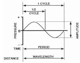
Figure 1-1C one cycle of a sine wave
Figures 1-1 A & 1-1B: Properties of a sine wave. Definitions (A); peak, rms and average values (B).
Another quantity is the magnitude , or the amplitude, of the alternating pressure of the propagating sine wave . While we may measure the static air pressure in a bicycle tire in terms of “pounds per square inch,” acoustics uses the International System (SI) of units in which air pressure is measured in pascals (newtons per square meter).
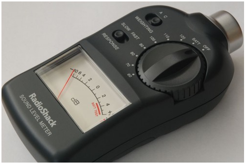
Sound Pressure Meter (SPL meter)
A sine wave with a maximum amplitude of unity has an rms (root-mean-square) value of 0.707 and an average value of 0.63.
The average value is simply the value of the signal averaged over one-half cycle, but the rms value gives us the effective steady-state value of the waveform. This is the value that we use in making power calculations, and it is directly proportional to the value that we measure with a sound level meter.
![]()
What is Sound ? cont.
How We Measure Sound: The Decibel (dB)
When we speak only in terms of sound pressure, we
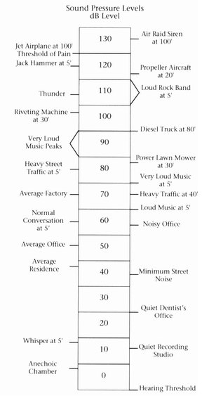
Sound Pressure Level Chart
are dealing with numbers which, from the softest audible sounds to the loudest, cover a million-to-one ratio. This would involve some rather large and clumsy numbers, and in the early days of telephone research, mathematicians simplified the notation with the introduction of the bel and the decibel . In using decibels we are expressing the level of one signal with respect to another (the term level is exclusively used in audio engineering for ratios given in dB). Fundamentally, the bel is defined as the logarithmic ratio:
![]()
logarithmic ratio
The Electrical representation of Sound
An audio signal is an electrical representation of a sound, in the form of a fluctuating voltage or current. Within the limits of audio equipment, the signal voltage or current fluctuates at exactly the same rate as the acoustical energy that it represents, and the amplitudes of the acoustical sound wave and the electrical audio signal are scaled proportionately. The amplitude, or strength, of an audio signal is called the signal level. Many different operating levels exist in audio systems. Level (acoustical or electrical) is specified in decibels.
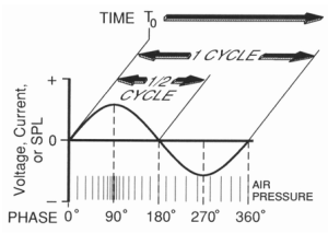
- Figure 1-2 Phase Diagram

Phase
The time relationship of a sound wave (or an audio signal) to a known time reference is called the phase of the signal. Phase is expressed in degrees. One complete cycle of a sine wave equals 360 degrees. The time reference may be an arbitrarily chosen, fixed instant in time. For example, Figure 1-2 shows a type of audio signal called a sine wave. A sine wave is a pure tone, a fundamental frequency with no harmonics (representing something like the sound of a flute). The phase of the sine wave is expressed on the graph in relationship to a time reference called To. This happens to be the start time of the wave, although it could be designated at any time within the wave’s period.
![]()
What is Sound ? cont..
The time reference may also be another signal. If it is, the reference signal must resemble the signal whose phase is being measured: we can meaningfully compare only objects that are alike, or at least related. For example, Figure 1-3 shows

Figure 1-3 Phase relationships between input & output signals
an audio signal processor with one input (VIN) and one output (VOUT), The phase of the output signal is expressed in relation to the input signal. In Figure 1-3(b), the output is said to be in phase with the input (both sine waves cross zero at the same time, going in the same direction). In (c), the output is 90 degrees out of phase with the input (one sine wave crosses zero when the other is at maximum, both going in the same direction). In 1-3 (d), the output is 180 degrees out of phase with the input (both sine waves cross zero at the same time, but going in opposite directions). Note that these phase relationships may change at different frequencies, and often do with real-world audio circuits.
Phase is very important in sound systems. The main reason that phase must be controlled is that it affects how sounds add together. When audio signals are mixed in a console, or when sound waves mix in the air, they add algebraically. Figure 1-4 shows

Figure 1-4 (a,b,c) Adding Sine Waves

the effect of phase on the addition of two sine waves of equal level and frequency, but at different phase relationships. In Figure 1-4 (a), the sine waves are in phase; they add to form a sine wave of twice the level of either one. In (b), the sine waves are 90 degrees out of phase. They add to form a sine wave that is 1.414 times higher in level than either one. In (c), the sine waves are 180 degrees out of phase; they totally cancel one another.
![]()
Developing relative pitch & Hearing audio frequencies
Below is a chart showing musical instruments and their relative frequency ranges, This will be an invaluable tool in developing your instrument and speaker system Equalization skills.
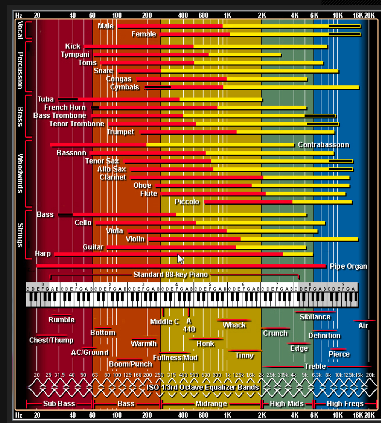
Instrument frequency range chart
FREQUENCY AS PITCH
Pitch and frequency are closely related. Pitch is one of the most obvious psychological attributes of musical sound, while frequency is a physical phenomenon. We perceive pitch from the frequency of a wave.
We will mention pitch and frequency in an interchangeable manner and will bypass the physiological, neurological, and psychological elements that are associated with pitch. We will refer to pitch and frequency in Hertz. Our ears can detect pitches from 20 Hz to 20,000 Hz.
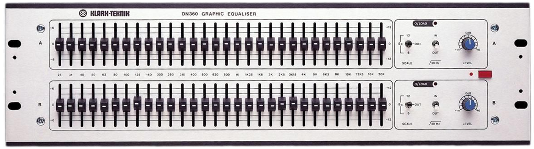
Klark teknik DN360 third octave EQ.
We do not hear all these frequencies equally however. We are more sensitive to mid-range frequencies than we are to low and high frequencies. This unequal sensitivity to frequencies also changes with levels. At low volumes, we do not hear low frequencies well at all. However, as listening levels increase, we tend to hear those frequencies at a more equal level to the midrange frequencies.
This is because as listening levels increase, the bones in our middle ear vibrate along with the ear drum increasing the perceived sound pressure level (SPL). At low volumes, these bones do not vibrate and hence we do not hear the low frequencies as well.
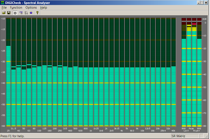
One Third Octave Analyzer
THE REAL TIME ANALYZER
The real-time analyzer (or RTA) may be the most elaborate and sophisticated piece of equipment in the sound man’s tool kit. It is used to obtain an instantaneous display of the frequency response of a sound system or signal processor. The RTA is basically a form of spectrum analyzer, optimized for audio use. It consists of a specified signal source, a calibrated microphone and preamplifier, signal amplifying and filtering circuitry, and a display. The most common type of display used in RTAs is an array of LEDs, although small, built-in CRT (oscilloscope-like) displays or a video output to a monitor are also found. The signal source normally used is a pink noise generator, although most RTAs will also respond to program material. The pink noise source is used to excite the system under test at all audio frequencies, with equal amplitude per octave. The output of the system is filtered in bands, usually one-third octave wide, and the signal amplitude in each band is determined electronically. The display is arranged to indicate the amount of energy in each band, as detected at the output of each filter. When used to evaluate a sound system, with a calibrated test microphone, the RTA is treated in much the same way as the SPL meter, and the same microphone-handling procedures apply to it. It may be used to measure the frequency response of sound systems at any point in a room or, outdoors, to determine the dispersion characteristics of a system. The RTA typically has a line-level input as well, and may be used to measure the characteristics of an individual signal processor or an entire chain through the preamp, mixer, signal processor and power amp (with appropriate padding after the power amp output).
![]()
Audio analyzer programs Introduction
L’Acoustics was the first company to introduce the “Line Array” speaker technology and the prediction software that guides the end user in properly hanging and aiming the speaker system to cover all areas of the audience.
While L’acoustics may be the most popular of these programs, other companies like JBL and D & B Audiotechnik all have their own proprietary programs.

Stadium diagram using L-Acoustics Sound Vision Mapping Software

D & B Audiotechnik Array Calc video tutorial
![]()
Venue acoustics and equalization techniques- in progress…..
![]()
![]()
Line array speaker system basic principals
Line arrays have been specially designed so when several units are combined vertically the whole system behaves as one single sound source. Generally speaking that’s what makes them different from the conventional speaker systems.
The horizontal configuration of the box, the distance between speakers, the cut-off frequencies and the design of the highs section are the features that allow for this behaviour.
On the Mids and Lows sections of line arrays there are two specific characteristics with which we may start this discussion. The first, which can be noticed immediately, is that the transducers are vertically assembled in one line, as close as possible to each other.
The second of these characteristics cannot be seen, but arises in any discussion about line arrays. It is the crossover frequency of the speakers. As we will see later on, this is an important part of the design of the system and cannot be modified without negative
effect on the behaviour of the whole system. These two characteristics have a lot in common and can be explained at the same time. However, for clarity purposes, we have preferred to introduce them separately. And so… to the theory!
There are two acoustic characteristics which would be desirable in a sound system.
The first would be the capacity of controlling the vertical directivity, so we can send acoustic energy only where it is needed, where the public is sitting, which would avoid sending it where it can be the cause of problems (like the ceiling of the theatres), or be
wasted when we are outdoors. The second desirable characteristic would be that the different individual sound sources sum coherently, behaving altogether as one single sound source, yielding a uniform sound pressure level along the distance. In the next sections we will explain in detail why these two characteristics are desirable and how they can be achieved.
In fig 1 we can see an example of a system with a poor vertical directivity control. The boxes are vertically assembled and as close as possible to one another. However, the transducers that reproduce the example frequency are at a distance from each other due to the vertical design of the box. The lobe that can be seen on top of the polar response
will cause a strong reflection, which will reach the audience area, delayed in time, compared to the direct sound. This will certainly affect the intelligibility.
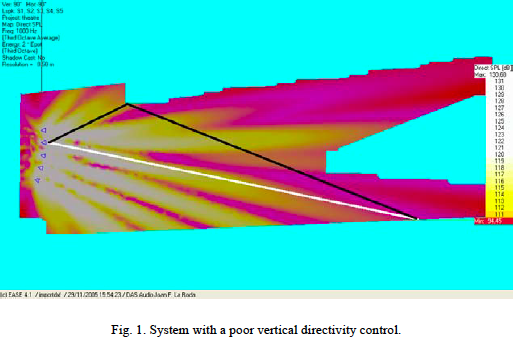
In fig 2 we can see a system with good vertical directivity control. The image shows clearly that the energy is concentrated where the audience is.
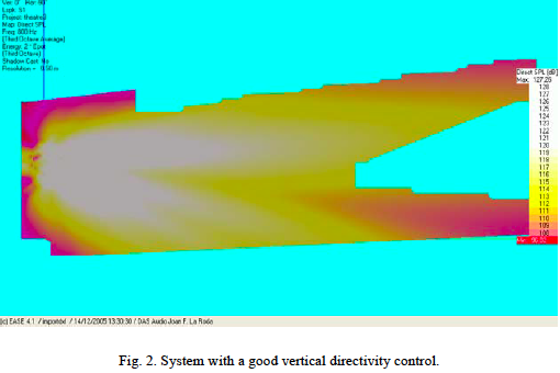
The vertical coverage angle needed to cover the audience area usually isn’t very large.
How can we configure a system if we want a narrow vertical coverage? There is a general principle which states that the smaller the distance between speakers of an array of boxes, the narrower the coverage becomes – and – of course the frequency plays a role here too.
We use this general principle in line arrays in order to get a narrow vertical coverage by assembling the transducers in a vertical line as close as possible to each other.
The horizontal coverage will be that of one single speaker.
![]()
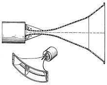
Horn loaded speaker system basic principals
A horn loudspeaker is a loudspeaker or loudspeaker element which uses an acoustic horn to increase the overall efficiency of the driving element(s). A common form (below Left)
Don Keele’s first constant directivity horn patent was assigned to Electro-Voice in 1978
consists of a compression driver which produces sound waves with a small metal diaphragm vibrated by an electromagnet, attached to a horn, a flaring duct to conduct the sound waves to the open air.
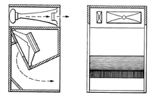
Another type is a woofer driver mounted in a loudspeaker enclosure which is divided by internal partitions to form a zigzag flaring duct which functions as a horn, this type is called a folded horn speaker.
A three-way Klipsch loudspeaker from the late 1970s employing a different exponential horn at each bandpass.
The horn serves to improve the coupling efficiency between the speaker driver and the air. The horn can be thought of as an “acoustic transformer” that provides impedance matching between the relatively dense diaphragm material and the less-dense air. The result is greater acoustic output power from a given driver.
The narrow part of the horn next to the driver is called the “throat” and the large part farthest away from the driver is called the “mouth”. The angular coverage (radiation pattern) of the horn is determined by the shape and flare of the mouth. Unlike cone speakers, horn speakers usually have rectangular apertures, with the width tailored for proper horizontal coverage angle, and height tailored for proper vertical coverage angle. A major problem of horn speakers is that the radiation pattern varies with frequency; high frequency sound tends to be emitted in narrow beams with poor off-axis performance.[2] Significant improvements have been made, beginning with the “constant directivity” horn invented in 1975 by Don Keele.
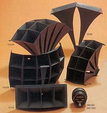
Altec Lansing multicell horn models from 1978.
The main advantage of horn loudspeakers is they are more efficient; they can typically produce 10 times (10 dB) more sound power than a cone speaker from a given amplifier output. Therefore horns are widely used in public address systems, megaphones, and sound systems for large venues like theaters, auditoriums, and sports stadiums. Their disadvantage is that their frequency response is more uneven because of resonance peaks, and horns have a cutoff frequency below which their response drops off. To achieve adequate response at bass frequencies horn speakers must be very large and cumbersome, so they are more often used for midrange and high frequencies. The first practical loudspeakers, introduced around the turn of the 20th century, were horn speakers. Due to the development in recent decades of more efficient cone loudspeakers, which have a flatter frequency response, use of horn speakers in high fidelity audio systems has declined.
OPERATION
Acoustic horns convert large pressure variations with a small displacement area into a low pressure variation with a large displacement area and vice versa. It does this through the gradual, often exponential increase of the cross sectional area of the horn. The small cross-sectional area of the throat restricts the passage of air thus presenting a high acoustic impedance to the driver. This allows the driver to develop a high pressure for a given displacement. Therefore the sound waves at the throat are of high pressure and low displacement. The tapered shape of the horn allows the sound waves to gradually decompress and increase in displacement until they reach the mouth where they are of a low pressure but large displacement.
A modern electrically driven horn loudspeaker works the same way, replacing the mechanically excited diaphragm with a dynamic or piezoelectric loudspeaker.
Modern horn designs typically feature some form of conical, exponential or tractrix taper. Roughly speaking, the slower the flare rate, the deeper and lower frequencies the horn will reproduce for a given length of horn. For example, a horn area growth rate of 30% per foot will allow reproduction down to about 30 Hz; 10 times area per foot provides midrange reproduction; 100 times area per foot is used in high frequency horns.
Modern high output horns also make the throat area of the horn smaller than the diaphragm area. This is called the “loading” or “compression” ratio of the horn. The compression ratio is the diaphragm area divided by the throat area. Typically for bass and midrange frequency the compression ratio is from low compression (1.5 to 1) to normal compression (2 to 1) to high compression (3.5 to 1). High frequency compression drivers sometimes have compression ratios as high as 10 to 1.
The higher the compression the greater the horn’s ability to properly couple the diaphragm to the air at the horn’s mouth, increasing efficiency, until the compression ratio is so high that it actually begins to impede cone motion. At this point the maximum sound output power from the horn (at a given distortion) will be reduced.
![]()
Monitor wedge basics
Stage monitor systems are speakers on stage pointing towards the performers to help them hear themselves. Monitor speakers are useful when amplified instruments are used with acoustic instruments and voice. Monitor speakers typically have their own power amplifier(s) and equalizers, Some are even self powered.
They are driven by a separate mix from the main or front of house console. This mix typically highlights the vocals and acoustic instruments so they can be heard over the electronic instruments and drums. The collection of monitor speakers, amplifiers, equalizers and monitor mixer if used is called the stage monitor system or simply monitors. In Britain the term foldback or foldback speakers is often used.
Floor monitors are compact speakers with an angled back that is laid on the floor. This angled shape gives the floor monitor its other name of wedge. The angle is typically 30 degrees which points the speaker back and up towards the performer. These speakers may be single small speakers such as the “hot spot” monitor by Galaxy Audio which are sometimes mounted on a microphone stand to get them closer to the performers ears. More often they are heavy duty two way systems with a woofer and a high frequency horn. A small floor monitor might use a 12″ woofer with an integrated high frequency horn/driver combination such as the JBL 4602A floor monitor.
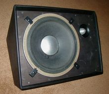
A JBL floor monitor speaker cabinet with a 12″ woofer and a “bullet” tweeter
A large floor monitor might use one or two 15″ woofers and a high frequency driver attached to a high frequency horn such as the EAWSM159zi stage monitor, The speaker might use a passive crossover or might be bi-amped with anactive crossover and separate amplifiers for the woofer and high frequency driver.
Active monitors
A recent trend has been to build the amplifier and associated sound processing equipment into the monitor itself. These monitors are called “active” or “powered” monitors. This design allows amplifiers with the right amount of power to be custom made for the speakers. Active monitors are typically bi-amped and have an active crossover with custom equalization to tune the monitor to have a flat frequency response.
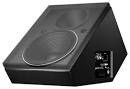
Meyer UM-1P active floor monitor
One of the first examples of this type of monitor is the Meyer Sound LaboratoriesUM-1P
![]()
![]()
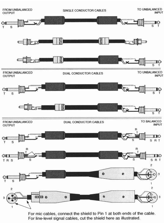
Balanced and unbalanced cables
In audio we use many different types of cables to connect various types of gear together, some of the cable lengths may be very short and some are extremely long, sometimes 300 to over 1000 feet long.
For this reason many types of cables and connectors have been invented to carry a multitude of different signals.
In a typical audio system all of the signal cables should be screened/shielded, other than those linking the power amplifiers to the speakers. The purpose of the screen or shield as its sometimes called is to intercept electrostatic interference and drain it away to earth before it can affect the signals passing along the inner wires. In an unbalanced cable the screen also forms the signal return conductor, whereas in a balanced cable the signal is carried by the two cores and the screen does not constitute a part of the audio signal path. The screen may comprise a woven copper braid, layers of multistrand wire wrapped around the inner cores in a spiral fashion, a thin layer of metal foil, or even conductive plastic. Each type of cable has its own strengths and weaknesses, in terms of screening efficiency, flexibility, cable capacitance, ease of termination and so on.
The type of multicore cable used to feed mic signals from the stage to the mixer comprises a number of small-diameter, individually-screened, twin-core cables housed in a common outer sleeve. Multicores are used in fixed installations for connecting the mixing console to the stage box and in conventional touring PA applications.
Balanced Wiring
 Signal connections on an analogue audio system may be either balanced or unbalanced. An unbalanced connection relies on a two-conductor cable, and in a screened audio cable this comprises a central core surrounded by a conductive screen.
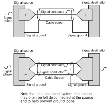
Although the screen (which is generally connected to ground) offers a significant degree of protection against electromagnetic interference, it’s still possible for traces of outside interference to be superimposed on the wanted signal. Balanced systems were developed to provide increased immunity to electromagnetic interference, and the principle is very simple. Instead of a two-conductor system, balancing is achieved by using three conductors – one of these is still an outer screen, while the other two are inner wires which carry the signal. Two signal cables are used here because one must be fed with a phase-inverted version of the signal, and if you look at the wiring details for a balanced connector (usually an XLR or stereo jack) you’ll see that the normal signal connection is usually referred to as ‘plus’ or ‘hot’, while the inverted signal is ‘minus’ or ‘cold’. At the receiving equipment, the minus (inverted) signal is inverted once again to bring it back into phase with the plus (normal) signal, and the two are combined. Why does this help? Because the two signal wires are physically very close to each other, it’s reasonable to assume that any interference will affect both conductors pretty much equally. When the minus signal is re-inverted at the receiving end, any interference on that line will also be inverted, so when the plus and minus signals are added the overall result is that the two interference signals cancel each other out, while the wanted signals combine.
The above illustration describes both balanced and unbalanced connection systems.
Ground Loops
Ground loops are a potential problem in any complex audio system where there are multiple earth paths between pieces of equipment and the mains supply ground. Your effects, processors, mixers, power amplifiers and back line may function perfectly in isolation, but if you connect them together the chances are that you’ll hear at least some background hum. If you’re lucky this will be fairly quiet, but if you’re unlucky it may prove to be so intrusive that your system becomes unusable.
Disconnecting the earth cables from various mains plugs is not a very safe option, especially in live situations, where performers are in close proximity with both grounded metalwork and mains-powered amplification.
Unbalanced Audio Systems
Simple audio systems rely largely on unbalanced audio connections, in which the signal travels along screened cables, each comprising a single insulated core surrounded by a screen, which is grounded to prevent outside electrical interference from reaching the signal. However, this isn’t a foolproof arrangement. All cable has an electrical resistance, and although this may be fairly low it is nonetheless discernible. If an electrical current is passed through any material that has an electrical resistance, a voltage will be produced between the two points of contact, and the magnitude of this will depend on the strength of the current and the resistance of the material, as stated by Ohm’s law. It therefore follows that, if a current is passed through the screen of a cable, there will then be a difference in voltage between one end of the screen and the other, which can cause problems with ground loops.
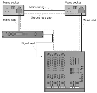
The Ground Loop
All audio systems include numerous mains-powered pieces of equipment joined to each other via cables, and there may be problems if all or part of this system uses unbalanced connections. All of the signal screens and mains earths will interconnect, and because cable possesses resistance there’s a real danger that interference signals will cause current to flow in the cable screens, resulting in audible signal contamination. While most interfering signals are pretty feeble, such as signals from distant radio transmitters, the 50/60Hz mains supply is a different matter. If you were to place a closed loop of wire inside a studio you’d be able to measure a 50/60Hz current flow in the wire, because the loop acts exactly like an inefficient transformer, picking up hum from wiring and transformers in other equipment. Even the most inefficient coupling of the mains supply into a wire loop will produce enough current to generate a voltage, which will be audible as hum. While the loop of wire in this example is purely hypothetical,  it illustrates how the earth and screen connections between just two pieces of equipment can form a closed loop, which will be affected by induced mains hum. In reality the wiring in a typical system is likely to create many ground loops, all of which will interact with each other.
Ground Loop Checklist
Don’t disconnect the earth leads from pieces of equipment that are designed to be used grounded. Build up your system a piece at a time, checking for hum at every stage. Cure any ground-loop problems before connecting any more equipment. If you don’t experience any hum problems when using standard leads, don’t feel that you have to fit ground-lifted cables.
move onto the next piece of equipment. Use balanced wiring where practical. Use ground-lifted leads when working with unbalanced equipment to ensure that each piece of equipment has only one direct earth path, either via a mains earth or a signal cable screen. Use a modified balanced cable when connecting unbalanced sources to balanced destinations, With two-pin mains equipment, or equipment running from mains adaptors, treat each device as you would for ground-lifted equipment, and ensure that just one of the signal cables provides a true ground. Additional connections should also be ground lifted (via resistors, in the case of unbalanced units) if further problems arise. If you don’t find a problem don’t feel that you have to provide a cure. Check individual items of equipment with a meter to determine which devices are equipped with built-in ground-lift resistors. Those that are ground lifted should be grounded via both the mains and one signal cable. Beware of problems caused by case-to-case contact. This is common in metal racks and is usually cured by using nylon mounting hardware. Make sure that all of your special cables are clearly marked, such as those which are equipped with resistors.
![]()
Instrument and speaker cables
Instrument Cables

Phone plugs are the norm for electric guitars. In order to prevent the hum and crackle that is often heard when the cable is unplugged from the guitar, some cables are available with a switch in the phone plug itself. The switch normally shorts the tip to the sleeve when the plug is not inserted in a jack. This grounds out the input to the guitar amp and prevents noise. When the plug is inserted in the guitar (or other instrument), the switch is opened by a small shaft protruding from the shoulder of the plug. Since the cable is not unshorted until it is connected to the guitar, noise is avoided. Such connectors are a good idea, but obviously the added complexity provides another opportunity for something to fail and cause noise or kill the signal. This type of switching phone plug is only for use in guitar cables and should never be used on a speaker cable since it can short circuit the output of the power amplifier.
Speaker Cables
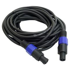
Speakon speaker cable
The function of a speaker cable is to provide a path of low resistance between the amplifier and the loudspeaker, and if the cable resistance compared to the impedance of the speakers to which it is connected is significant, the power will be shared between the speaker and the cable. Using inadequate cable will also reduce the damping factor of the amplifier, where the damping factor is defined as the output impedance of the amplifier divided into the impedance of the speaker to which it is connected. This is an important point, because the higher the damping factor the greater the amplifier’s ability to produce a tight, accurate bass end. The damping factor becomes less effective as the cable impedance rises.
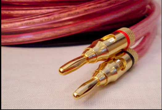
Speaker cable w/ banana plug male ends
Use the shortest, thickest speaker leads you can, make sure speaker cables are roughly the same length, and use low-resistance connectors such as Speakons or XLRs. 1/4″ Jack connectors are a poor compromise, even on low-powered systems.
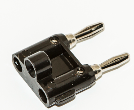
Dual Banana plug male conector
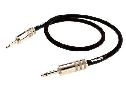
Quarter inch to quarter inch cable
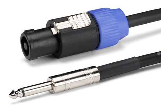
Speakon to quarter inch cable
![]()
Midi cables and fiber optic cables
Midi Cables
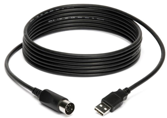
Midi- 5 pin din to USB cable
MIDI (/ˈmɪdi/; short for Musical Instrument Digital Interface) is a technical standard that describes a protocol, digital interface and connectors and allows a wide variety of electronic musical instruments, computers and other related devices to connect and communicate with one another.[1] A single MIDI link can carry up to sixteen channels of information, each of which can be routed to a separate device.
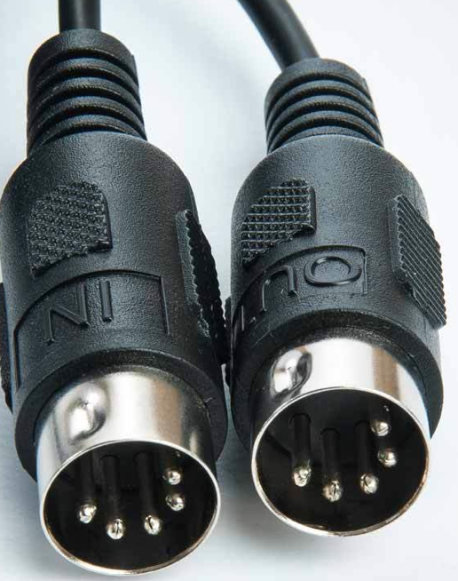
Midi- 5 pin din to din cable
MIDI carries event messages that specify notation, pitch and velocity, control signals forparameters such as volume, vibrato, audio panning, cues, and clock signals that set and synchronize tempo between multiple devices. These messages are sent via a MIDI cable to other devices where they control sound generation and other features. This data can also be recorded into a hardware or software device called a sequencer, which can be used to edit the data and to play it back at a later time.[2]:4
MIDI technology was standardized in 1983 by a panel of music industry representatives, and is maintained by the MIDI Manufacturers Association (MMA). All official MIDI standards are jointly developed and published by the MMA in Los Angeles, California, US, and for Japan, the MIDI Committee of the Association of Musical Electronics Industry (AMEI) in Tokyo.
Fibre Optic Cables
An optical fiber (or optical fibre) is a flexible, transparent fiber made by drawing glass (silica) or plastic to a diameter slightly thicker than that of a human hair. Optical fibers are used most often as a means to transmit light between the two ends of the fiber and find wide usage in fiber-optic communications, where they permit transmission over longer distances and at higher bandwidths (data rates) than wire cables. Fibers are used instead of metal wires because signals travel along them with lesser amounts of loss; in addition, fibers are also immune to electromagnetic interference, a problem which metal wires suffer from excessively. Fibers are also used for illumination, and are wrapped in bundles so that they may be used to carry images, thus allowing viewing in confined spaces, as in the case of a fiberscope. Specially designed fibers are also used for a variety of other applications, some of them being fiber optic sensors and fiber lasers.

Common fibre optic connector types1
Optical fibers typically include a transparent core surrounded by a transparent cladding material with a lower index of refraction. Light is kept in the core by the phenomenon of total internal reflection which causes the fiber to act as a waveguide. Fibers that support many propagation paths or transverse modes are called multi-mode fibers (MMF), while those that support a single mode are called single-mode fibers (SMF). Multi-mode fibers generally have a wider core diameter and are used for short-distance communication links and for applications where high power must be transmitted.[citation needed] Single-mode fibers are used for most communication links longer than 1,000 meters (3,300 ft).[citation needed]
An important aspect of a fiber optic communication is that of extension of the fiber optic cables such that the losses brought about by joining two different cables is kept to a minimum. Joining lengths of optical fiber often proves to be more complex than joining electrical wire or cable and involves the carefully cleaving of the fibers, perfect alignment of the fiber cores and the splicing of these aligned fiber cores. For applications that demand a permanent connection a mechanical splice which holds the ends of the fibers together mechanically could be used or a fusion splice that uses heat to fuse the ends of the fibers together could be used. Temporary or semi-permanent connections are made by means of specialized optical fiber connectors.
![]()
![]()
Compressors and there Controls
Compressors
A compressor performs essentially the same task as manual gain riding, but it does it both quickly and automatically. The aim of compression is to reduce the difference in level between the loudest and quietest sounds. The compressor monitors its own output level by electronic means to find out what the levels are doing, although some designs monitor the input level. The part of the circuit that monitors the signal level is called the side chain, and it follows the envelope of the audio signal. This level is then compared to a fixed threshold level, which is set by the user, and when the signal exceeds the threshold the side chain generates a control signal to reduce the signal gain using a VCA (Voltage-Controlled Amplifier). Figure 1 shows the simplified block diagram of a typical compressor.
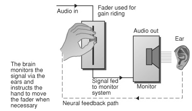
Manual gain riding
Basics Of Compression
![]()
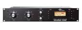
DBX 160A Vca style compressor
A compressor performs essentially the same task as manual gain riding, but it does it both quickly and automatically. The aim of compression is to reduce the difference in level between the loudest and quietest sounds. The compressor monitors its own output level by electronic means to find out what the levels are doing, although some designs monitor the input level. The part of the circuit that monitors the signal level is called the side chain, and it follows the envelope of the audio signal. This level is then compared to a fixed threshold level, which is set by the user, and when the signal exceeds the threshold the side chain generates a control signal to reduce the signal gain using a VCA (Voltage-Controlled Amplifier). Figure 1 shows the simplified block diagram of a typical compressor.
Universal audio 1176 Fet style compressor
The level above which the compressor decides to turn the gain down is known as the threshold. The level of gain reduction depends on the compressor’s ratio control. Typically, this is variable from 1:1 (no effect at all) to infinity:1, where the output level is never allowed to rise above the threshold. The higher the ratio, the more gain reduction is applied to signals exceeding the threshold. Figure 2 shows a graph of the input versus the output of a compressor set for different ratio settings.Compressor Controls
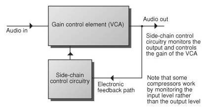
Figure 2- Compressor block diagram
Soft-Knee Compression
For those applications where less obtrusive compression is required, the soft-knee compressor may prove more useful. The main difference between a soft-knee and a conventional compressor is that, in the case of a soft-knee device, the gain is reduced progressively, starting a few decibels below the threshold, instead of everything happening as soon as the signal hits the threshold. Not all soft-knee compressors have a ratio control, however; some are completely automatic, which means that the degree of compression can be controlled by a single knob.
Attack & Release Controls
![]()
Avalon Vt737 mic preamp- tube compressor
Unless the compressor is fitted with an auto attack and release function it will probably be fitted with both attack and release time controls. Attack sets the reaction time of the compressor (how long the device takes to respond when a sound exceeds the threshold) and release determines then length of time the gain will take to return to normal once the signal level has dropped back below the threshold. You’ll usually try to find the shortest release setting that doesn’t result in obvious ‘pumping’, and the correct setting for most pop music applications is around a quarter of a second. The attack time should be fixed to its fastest setting to acquire tight control of vocals, but a slightly longer attack time allows the leading edge of transient sounds such as drums or guitars to cut through more strongly. If a two-channel compressor is used on a whole stereo mix or stereo subgroup it’s important that the unit has a Stereo Link switch. Without this the loudest channel will receive the most compression, which can cause the stereo image to shift from side to side.
Limiters
A limiter is basically a compressor with a very high ratio and a quick response time. Limiting is a vitally important function in PA work because it’s very often only the limiter that stands between the drivers and a smoky death! If a general-purpose compressor is used as a limiter it must be set to its fastest attack time, but using a dedicated limiter is a better option if you don’t already have them built into your crossovers or system processors.
![]()
Noise Gates and there Controls
Noise Gates
![]()
Drawmer DS201 Noise Gate
A gate is little more than an automatic switch which turns off the audio signal path when the signal falls below a threshold set by the user to mute low-level noise during pauses. Like compressors, most commercial gates have attack and release parameters that determine how quickly the gate opens and closes. The fastest attack settings allow percussive transient sounds to pass through cleanly, while a slow attack forces the gate to open more gradually. Unwanted clicking can be avoided when gating non-percussive sounds by slowing the gate’s attack time down to a few milliseconds. Percussive sounds usually require the fastest attack time possible in order to maintain their transient impact. A variable release time means that the gate can close gradually when sounds with a slow decay are being processed. If the gate were to close abruptly the tail ends of naturally decaying sounds, such as reverb tails or decaying plucked guitars, would be cut off. Figure 4.3 shows the attack and release phases of a typical gate.
Side-Chain Filtering
An example of a more elaborate gating process is side-chain filtering, which usually comprises a pair of shelving equalisers – one high pass and one low pass – connected in series with the gate’s side chain. By adjusting the upper and lower limits of the filters it’s possible to make the gate open only when it ‘hears’ the band of frequencies between the two filter settings. This can help enormously in situations where spill from other instruments is likely to cause false triggering.
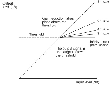
Figure 3- Attack & Release of a Noise Gate
Filtering is often used when miking drum kits in order to prevent crash cymbals from opening tom gates, and this is achieved by lowering the upper filter frequency to exclude the high frequencies of the cymbals but still allow the sound of the tom to trigger the gate.
![]()
BSS DPR 504 Quad Noise Gate
![]()
In Ear system mixing- in progress…
![]()
Expanders and there Controls
Expanders
Expanders increase the difference in loudness between quieter and louder sections of audio making quiet sounds quieter and loud sounds louder. They are pretty much the opposite of compressors working by turning down the volume when the signal level falls below the threshold and turning the volume back up when the signal level goes above the threshold.
Expanding is useful when you want to increase the dynamic range of the audio. For example, when you have a recording and want to reduce the volume of the quieter parts so you don’t notice the noise as much.
A side effect of expanders is that they change the way sounds decay and can end up silencing quieter parts of your audio that you want to keep.
The main controls on an expander are: attack and release times, and ratio.
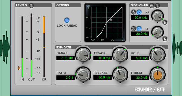
Digidesign Expander/Gate plug-in
The attack time sets how fast the expander responds to signal levels above the threshold.
The release time sets how fast it reacts when the signal level drops below the threshold.
The ratio determines how much to turn the volume down. A higher ratio results in the volume being turned down more. A very high ratio of 12:1 or more is considered a noise gate.
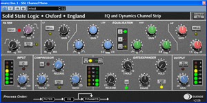
SSL EQ. & Dynamics strip
![]()
![]()
What is “”Reverb” and it’s uses
Reverberation is a very familiar effect, and in nature it is created when sound reflects from surfaces inside a confined space, such as a building. Although the concept is simple the resulting reflection patterns are immensely complex, which is why electronic reverb processors require powered digital signal processing chips for their operation. Most reverb units include algorithms for halls, rooms, chambers and plates (a mechanical studio reverb device based on a large metal plate), as well as non-natural reverbs such as gated and reversed versions. Figure 1- illustrates how reverb develops from a percussive sound. The basic algorithms also include parameters for adjusting the relative high-frequency and low-frequency decay times to emulate the effects of different types of room or soft furnishings.
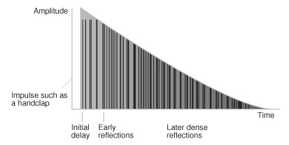
Figure 1- Reverb development from a percussive sound
Reverb can also be an inspirational creative tool, increasing the range of ‘virtual spaces’ you can experiment with. What’s more, a reverb unit can provide reverberation treatments which would never occur naturally, but which are nevertheless useful tools for stereo mixing within popular music genres — what we hear when we listen to modern commercial records is often very different from a natural reverberant environment, for any number of artistic and commercial reasons.
Most artificial reverberation in use today is implemented with digital technology,
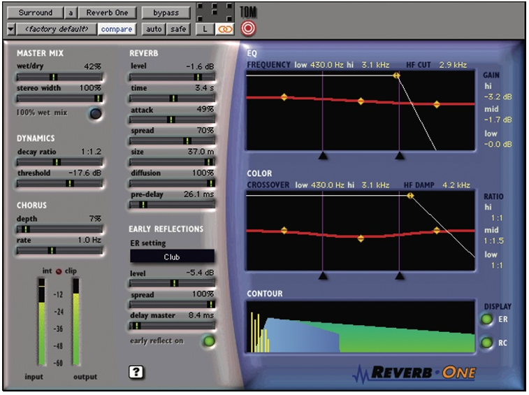
Reverb one plug in
because microprocessors are well suited to this task — simulating the reflection of a sound is, at its most basic level, merely a question of storage and delayed recall. However, attaining realistic yet easily controllable simulations of the immensely complex reflections within real acoustic spaces is no mean feat, even with the best DSP, and the most convincing and flexible simulations can cost thousands of dollars. Fortunately, digital reverberators have been around since the ’80s, so much of what was once ‘flagship’ technology is now becoming available at much more modest prices.Affordable digital reverberation comes in a variety of forms. In addition to dedicated stand-alone units, from the likes of Alesis, Lexicon, Sony and Yamaha,
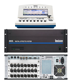
Lexicon 960L reverb unit w: remote control
there are also software plug-ins which provide similar functionality within the graphical environment of your computer sequencer or DAW, and many workstations, synthesizers and multi-effects units now include reverberation amongst their feature set. However, algorithms in multi-purpose devices and ‘native’ plug-ins are often run on limited processor resources so their quality can be limited. Quality reverb is fundamental to most professional recordings and live concerts.
Using too much reverb or too long a setting smothers the timbral and rhythmic subtleties of individual parts, and can cause vibrant mixes to become flat and distant. Reverb needs to suit the music it is applied to — slowly unfolding New Age music might be fine with lots of long rich reverb, but that same effects use is unlikely to suit most fast-paced rhythmic music. Remember that reverb can help to create front-back perspective in your mix, so don’t apply it with a trowel unless you want your mix to lose its sense of contrast and depth. It is also worth realising that long reverbs will exaggerate the weaknesses of budget reverberators, and that such units give their best results only when used carefully and in moderation.
There are also a few specific things to avoid for most popular genres. Stereo pad sounds probably don’t need much reverb — they often have lots already and, in any case, are already designed to fill gaps in an arrangement, so adding extra reverb usually verges on overkill. Large amounts of long reverb are also less than suitable for most basses and low drums — you’ll soon find your mixes disappearing into the mud if you overdo it, and many mix engineers avoid reverb on low instruments altogether.
As a general rule, if the intelligibility of words is important, then neither the effect level nor the reverb time should be too high. Increasing the Pre-delay time can also help to keep words clear.
Beyond that, everything depends upon the role of the singers and on the type of music. For choral recording, use longer reverb decay times with increased High-frequency Damping and decreased Low-frequency Damping in order to simulate typical choral venues. However, such a setting would be completely unsuitable for a pop lead vocal, where it would position the vocal too far away and muddy the texture.
However, our most commonly received queries concern lead vocals within popular chart styles. In addition to ensuring the clarity of the words, it is also wise to keep reverb level and decay times low — you want to keep the vocal close to the front of your mix. It’s also worth keeping the reverb fairly bright, as this can help further highlight the sound. If this accentuates sibilance too much, you can always de-ess the feed to the reverberator.
Before abandoning reflection-based effects completely, experiment with using only the Early Reflections part of a reverb program. If you can’t isolate this on your particular unit, then you can always mock up something similar with a multitap program. Ordinary single-tap delays can also nicely thicken up sounds in much the same way as reverb, without obscuring too much detail in your mix.
Equalisation can be used to enhance the front-back perspective of your mixes — toning down a little high end can simulate the increased air-damping which affects sounds travelling from more distant sources. If you feel you just need to give a sound a stereo spread, why not try a little stereo flanging or chorus — you could even try using a fast, shallow autopanning program to slightly smear the sound across the stereo image. If you feel that an instrument is little thin without reverb, you might try compressing it a little to emphasise low-level detail. Some engineers prefer not to compromise the dynamics to this extent, instead mixing a heavily-compressed feed in with the unprocessed signal. If this doesn’t go far enough, then try viciously compressing a short mono Early Reflections program (without pre-delay) and mixing a small amount of that in with your original sound for a more pronounced effect.
All of the above uses and precautions can be used in the “Live” concert environment by blending in with the venues already natural reverb sound and decay times.
Working with the venue acoustics almost always will work better than trying to beat them with volume coming from your effect!
![]()
What is Digital “Delay” and it’s uses
The DDL is the basic component of a number of familiar effects, some of which are produced by modulating the delay time. The simplest DDL effect, however, is a single repeat which uses no modulation and no feedback. Short delays of between 30ms and 100ms are used to create slap-back echoes, while longer delays produce a distinct single echo. Also, delays timed to coincide with the tempo of the song can occasionally be effective. Multiple equally-spaced delays can be obtained by increasing the feedback value, while using a multi-tapped delay enables a less rhythmic echo effect to be created. For the best effect, however, the delay times of the various tapes should not be set to exact multiples of each other. This simulates the multihead tape echo system, on which the heads were often spaced at irregular intervals. The addition of feedback causes the echo decay to become quite complex, and this effect is popularly used with electric guitars, vocals and instruments such as lead synths, saxophones and flutes. A number of modern units feature a tap tempo facility, by which you simply tap your foot on a switch at the tempo of the song and the delay time will be set to the time interval between your taps. Obviously the maximum delay time can’t exceed the maximum delay time of your DDL, but this is a very quick and easy way of making sure your that repeats are in time with the song.
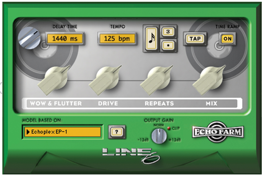
Echo Farm Delay plug-in
Delay Modulation
Modulating the delay time with an LFO causes the pitch of the delayed signal to waver both sharp and flat at the rate set by the speed of the LFO. The depth of modulation determines the extent of the sound’s sharpness or flatness. The simplest modulation effect is pitch vibrato, which only uses the delayed sound – the original sound is turned off by using the mix parameter. The sound emitted by the output will be delayed slightly, but if the delay time is set to less than 10ms it will be too short to notice.
Phasing
To convert vibrato into phasing, you should set the mix parameter to provide equal amounts of dry and delayed sound and experiment with delay times between 1ms and 10ms. As you adjust the speed and depth of modulation you’ll hear the individual harmonics that make up the sound moving in and out of phase with each other, which has the effect of filtering the sound in a very dynamic and complex way. You’ll probably recognise the effect as being similar to that obtained with guitar phaser pedals. Try switching on your unit’s feedback invert function, if it has one, as this also affects the harmonic structure of the effect.
Flanging
![]()
Lexicon Pcm 42 Delay unit
Flanging dates back to the Sixties, and was first created by simultaneously running two tape machines carrying copies of the same music and then mixing the two outputs with precisely equal levels. If the two machines are perfectly in sync (synchronised) with each other then the two signals combine normally, but if the timing between the machines drifts the listener hears a phasing effect, caused by comb filtering. You can control the effect by deliberately slowing down first one machine and then the other by placing your hand on the supply reel. Flanging can be approximated digitally by adding a delayed signal to the original sound and then modulating the delay time of the delayed signal. The settings for flanging are similar to those used for phasing but with longer delay times, typically 10–50ms, and the feedback value is increased to make the effect more resonant. As with phasing, inverting the phase of the signal fed back to the input allows different harmonics to be accentuated by filtering. Try both and decide which you prefer.
Chorus
Chorus is essentially the same as vibrato, although with an equal proportion of the dry sound mixed in. The idea of chorus is to produce the illusion of two instruments playing together by simulating the slight differences in timing and pitching that occur between two or more performers playing identical parts on identical instruments. By setting a longer delay time than for vibrato – for example, between 30ms and 150ms – the effect of the differences in timing between instruments becomes more pronounced. Chorus was first developed for use on electric guitars and synth string machines, but it can be used on virtually anything, from fretless bass to synth pads. You can also fatten up a mono chorus by panning the original, untreated sound to one side and the modulated delay to the other, which results in a wide, moving sound source that appears to hang between the speakers.
P.A. system delay
The digital delay is also used to compensate for speaker cluster time differences.
When using multiple speaker arrays to cover areas of the venue where the main speaker cluster can not cover, the systems engineer has to make sure that the “Sub woofers” “side hang” and “delay” speaker clusters are all in time with the main speaker cluster.
If this calculation were left undone, intelligibility would be very poor as the listeners would hear sound arriving from multiple speaker arrays at different times.
Calculating time and distance
The speed of sound is the distance travelled per unit time by a sound wave propagating through an elastic medium. The SI unit of the speed of sound is the meter per second (m/s). In dry air at 20 °C, the speed of sound is 343.59 meters per second (1,127 ft/s). This is 1,236 kilometers per hour (768 mph; 667 kn), or a kilometer in 2.914 s or a mile in 4.689 s.
![]()
Delay charts and time -vs- distance measurements
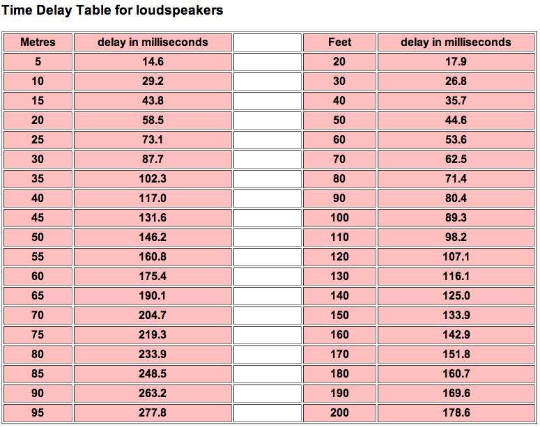
Time Delay Table for loudspeaker calculations

BPM Time delay chart for music intervals
Website for down loadable delay calculators can be found at:
http://www.doctorproaudio.com/doctor/calculadores_en.htm#calc_tiempo-distancia
![]()
![]()
Discussion on mic types and what they are best used for
A wide range of dynamic and capacitor microphones are used in recording and live sound applications – especially at the lower end of the market – dynamic mics are the most commonly-used model because of their affordability and robust construction. However, there are capacitor and back-electret capacitor microphones that offer advantages in certain live applications, and some are surprisingly cheap.
Impedance
Microphones are generally available in high-impedance unbalanced or low-impedance balanced varieties. Virtually all professional audio equipment uses the low-impedance balanced format, and if your microphone connects via a three-pin XLR at the base of the body it almost certainly falls into this category. Conversely, a mic with a fixed cable terminating in a single-pole jack plug is likely to be high impedance unbalanced. High-impedance mics are used mainly with older all-in-one mixer amplifiers, and cable lengths should not exceed 15 feet or so with this variety or the high end will suffer and interference may become a problem. Low-impedance balanced mics, however, can be used with much longer cables with no loss of signal quality.
Dynamic Microphones
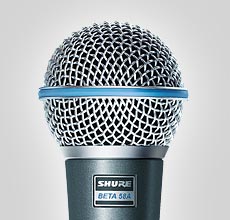
Shure Beta 58 dynamic mic
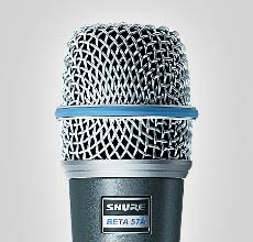
Shure Beta 57A mic
Dynamic mics are relatively inexpensive, mechanically robust, and require no electrical power to operate, which makes them attractive for both recording and live-sound applications. At the heart of the dynamic microphone is a rigid, lightweight diaphragm attached to a coil of extremely thin insulated wire. This coil is suspended within a magnetic field created by a permanent magnet, much like a loudspeaker voice coil, and as the diaphragm assembly moves backwards and forwards in response to sound a small electrical current is generated. Because the diaphragm is moving in response to sonic vibrations the output signal is a direct electrical representation of that sound. The diaphragm, voice coil and magnetic assembly are incorporated into a single unit, known as the microphone capsule, and this is usually visible if the protective wire basket (wind screen) is removed.
The sound energy must move both the microphone’s diaphragm and the coil which is attached to it, and because the assembly has a measurable mass any increase in the speed of its movement is countered by it’s inertia. Inertia resists acceleration, and a vibrating microphone diaphragm has to accelerate and decelerate many times each second as the diaphragm moves first one way and then the other.
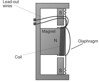
Figure 1.1 Schematic of a dynamic mic
In practice this places the upper frequency limit on dynamic mics around 16KHz, though some ingenious designs have managed to push this figure a little higher. Figure 1.1 shows the schematic of a typical dynamic microphone.
Capacitor (Condenser) Microphones
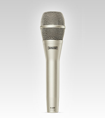
Shure KSM9 wired mic
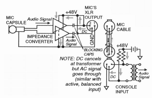
How phantom power and audio share the same cable.
Capacitor microphones, sometimes known as condenser microphones, are generally considered to be the most accurate type of microphone because they are able to respond to very high audio frequencies and they can be made to be sensitive enough to work with quite or more distant sound sources. Capacitor microphones don’t have voice coils but they still need a diaphragm, although this can be much thinner and lighter than that in a dynamic mic, which is why the microphone can respond more effectively to a range of high frequencies.
As the diaphragm vibrates, it’s distance from the stationary metal plate varies accordingly, and if a fixed electrical charge is applied between the diaphragm and the plate a corresponding change in electrical voltage is produced. This change in voltage is then amplified by circuitry within the microphone, which is why the capacitor microphones need electrical power in order to operate. Power is also needed to provide the electrical charge on the diaphragm, as been seen in figure 2.2
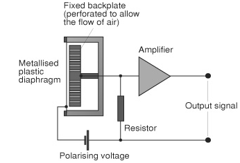
Figure 2.2 Schematic of a capacitor mic
Ribbon Microphones
Ribbon microphones employ a transduction method that is similar to that of dynamics. Figure 3.3 illustrates the construction of a typical ribbon element. A very light, thin, corrugated metal ribbon, The ribbon is clamped at the ends, but is free to move throughout its length. When sound strikes the ribbon, the ribbon vibrates in response. As is the case with the dynamic coil element, the moving ribbon cuts the magnetic
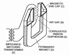
- Figure 3.3 Schematic of a ribbon mic
lines of force in the air gap, and a voltage is thereby induced in the ribbon. The voltage is very small and the ribbon impedance very low, so all ribbon microphones incorporate a built-in transformer. The transformer serves the dual functions of boosting the signal voltage and isolating the ribbon impedance from the load presented by the input to which the microphone is connected. Early ribbon microphones were extremely fragile. The ribbon could be damaged simply by blowing or coughing into the microphone! Not many microphone manufacturers now make ribbon units, but those that are available are much more rugged than older units. All but a few modern ribbon mics remain more fragile than dynamic or condenser units, so they are used primarily in recording (a couple of notable exceptions are used for reinforcment). Ribbon microphones usually have excellent sonic characteristics, with great warmth and gentle high-frequency response. They also have excellent transient response and very low self-noise. For these reasons, some ribbon mics are prized as vocal microphones, and are also very effective with acoustic instruments.
Pressure Zone Microphones
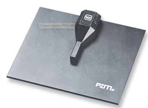
Crown Audio PZM 6D
Originally developed for recording and implemented using condenser instrumentation elements, the pressure zone principle offers certain benefits. Among these are good imaging qualities and, if the element is mounted on a floor or wall, freedom from path-length cancellations. Low-frequency response of the pressure-zone microphone is directly related to the size of the boundary plate. The larger the plate, the better the pickup of lows. Pressure-zone microphones are sometimes used in sound reinforcement, but since they are inherently omnidirectional, they offer little help with feedback. Recently, directional units have been developed to deal with this problem, and are finding some application in conferencing situations as well as instrument amplification.
Wireless Microphone systems
A wireless microphone system is a small scale version of a typical commercial FM broadcasting system. In a commercial broadcasting system, a radio announcer speaks into a microphone that is connected to a high-power transmitter in a fixed location. The transmitted voice is picked up by an FM receiver and heard through a speaker or headset. In a wireless microphone system, the components are miniaturized but the same principles apply. The transmitter is small enough to fit into the microphone handle or into a small pocket sized case. Since the microphone and transmitter are battery powered, the user is free to move around while speaking or singing into the mic. The transmitted voice is picked up by a receiver that is wired to a speaker. Two types of microphones are available with wireless mic systems: the handheld mic, with a transmitter in its handle; and the lavalier mic, which is small enough to be concealed as a lapel pin or hung around the neck. Lavalier mics are wired to miniature body-pack transmitters, which fit into a pocket or clip onto a belt.
Who uses wireless mics
Wireless microphones are widely used today in television and videotape production. They eliminate the need for stage personnel to feed cables around cameras, props, etc. For location film production, as well as ENG (Electronic News Gathering) and EFP (Electronic Field Production), wireless mics make it possible to obtain usable first take sound tracks in situations that previously required post-production dialogue looping. The cost saving can be significant. Handheld mics are used by performers on camera where they provide the freedom needed to move around the stage and gesture spontaneously. They are used by speakers and entertainers who need to pass the mic from one person to another. In concerts, handheld wireless mics permit vocalists to walk and dance around the stage and even into the audience without restriction and with no chance of shock in the event of rain. Lavalier mics are used in game shows, soap operas and dance routines. They eliminate the need for boom mics and help to alleviate visual clutter. Lavalier mics are used by MCs, panelists, lecturers, clergy, stage actors, and dancers because they can be concealed easily and provide hands-free mobility. Some lavalier transmitter models have high impedance line inputs that accept cords to create wireless electric guitars.
What is the background of wireless mics
Technological advances since the late 1960s have tremendously affected both the size and performance of wireless mics. Until that time wireless mics were large and used miniature vacuum tubes, offering limited dynamic range and poor audio quality. The development of semiconductor technology in the late 1960s reduced these problems significantly.
Technology in the early 1970s introduced the integrated circuit compandor which was incorporated into wireless mics to reduce noise. At about the same time, the FCC authorized the use of frequencies in TV channels 7-13 for wireless mics. Thus the wireless microphone’s most serious problem, radio interference from other services, was virtually eliminated. Later, the application of diversity reception minimized the problem of dropouts (transmission losses due to cancellation of radio waves), greatly improving system reliability. Today’s wireless mics perform as well as conventional wired mics. In the 1980s, wireless mics are being manufactured with improved dynamic range and smaller transmitters, a result of better compandor integrated circuitry and advanced circuit design techniques. A variety of standard microphones with different sound characteristics is available.
Radio frequencies used
There are no international standards for wireless mic radio frequency allocations. Performance is not controlled for transmitter power limits, frequency stability, or RF bandwidth occupancy. Wireless mics could therefore, theoretically, operate at any frequency. Certain frequency bands, are more commonly used.
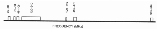
Figure 1.0 International frequency band chart
Commonly used international frequency bands
In the United States, the FCC regulates the operation of wireless mics at specified frequency bands. Frequency bands typically used are shown in Figure 1.1 The applicable Federal Communications Commission regulations are as follows:
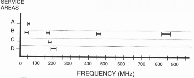
Figure 1.1 U.S. frequency band chart
• Low power communication devices may operate in the 49.81 MHz to 49.90 MHz band (Figure 10-32 (a)). Power is limited to 10,000 µV/M radiation at a 3 meter distance (approximately 1 to 5 mW) and with a 5 kHz audio frequency limit. This segment of the RF spectrum is susceptible to man-made noise generated by auto ignition, flourescent lights, dimmers, etc. The restriction imposed by the FCC on low-power equipment aggravates the problem of signal-to-noise ratio in this band. Because these frequencies are evenly spaced (15 kHz apart), only three wireless mics can operate simultaneously without RF intermodulation products causing interference. • Wireless mics are permitted to operate in the commercial FM broadcasting band, providing their power is not greater than 50 µV/M radiation at 15 meters. With this power restriction, it is not practical to use this band for professional applications in which reliable transmission performance is expected. • Wireless mics may operated on a shared basis with business radio service. Continuous radio transmission is authorized if the transmitter power is limited to 120 mW. The business radio service frequencies for wireless mics are: 30.76 MHz to 43 MHz, VHF low-band; 150 MHz to 173.4 MHz, VHF high-band: 457MHz to 470 MHz, UHF low-band; and 806 MHz to 866 MHz, UHF high-band (Figure 10-32 (b)). At 150 MHz and higher, man-made noise decreases significantly. With the higher power and larger transmission bandwidth allowed by the FCC, along with many more available frequencies and the shorter antenna requirement, operation in the VHF high-band and higher is desirable. The major disadvantage is interference from other business radio services. An operating station license is required and the transmitter must be type accepted under FCC regulations. Contact your local FCC office for aForm 25 if you want to obtain a license. Anyone can operate a wireless mic system at these frequencies. Specific frequencies designated in this part of the regulation for wireless mics are known as “B frequencies.” The bands are from 169.445 MHz to 170.245 MHz, from 171.045 MHz to 171.845 MHz , from 169.505 MHz to 170.305 MHz and from 171.105 MHz to 171.905 MHz (Figure 10-32 (c)). “B” frequency transmissions must not exceed a bandwidth of 54 kHz and output power of 50 mW. • For broadcasting, video production, and filmmaking applications, wireless mics may operate in the 174 MHz to 216 MHz range (TV channels 7 thru 13), on a non-interference basis. (Figure 10-32(d)). This means that for a given location, wireless mics may operate on unused TV channels. Transmitter power is limited to 50 mW. An operating station license is required for broadcasters and filmmakers and the transmitter used must be type accepted under FCC regulations. This VHF high-band offers the best operating area for wireless mics. It is free of citizens band (CB) and business radio interference, and any commercial broadcast stations that might cause interference operate on a schedule, and thus can be avoided easily.
![]()
Wireless Microphone systems cont.
Transmission Loss
There is a calculated transmission loss between transmitter and receiver through use of an isotropic antenna. Less transmitter power is required for an equivalent signal strength at the receiver as frequency is lowered. One problem with wireless microphones is the difficulty in designing antennas that are small but efficient in the VHF low-band area. However, for the VHF high-band, small and efficient antennas are practical. Interference from other radio services is the major problem at both VHF and UHF. The only clear channels available are the unused TV channels in a given location and the “B” channels. For touring groups the TV channels become a problem, as a clear TV channel in one city may not be clear in another. Therefore, the “B” channels are recommeded for this purpose.
Dropout
Loss of reception at the receiver of a wireless mic due to radio wave cancellation called multipath reflections is usually referred to as dropout. This problem has several possible sources. Dropout characteristics are different between VHF and UHF frequency bands. The dropout zones are much shorter at UHF where rapid flutter is often heard. Loss of reception may also be caused by a transmitter being too far from the receiver. This may be corrected by relocating either the transmitter and receiver antennas closer to each other. The power of a signal received by an antenna is a critical factor in causing dropout. When examining practical solutions and limitations in alleviating dropout, it is important to consider that not all of the power transmitted will reach the receiver. A wireless mic transmitter radiates power in many directions simultaneously, depending on the specific mechanical configuration of the antenna system. This makes the transmission vulnerable to many types of interference. System performance is degraded by path losses due to interfering objects between the transmitter and receiver, such as other equipment or people, as well as by the position of the transmitter antenna and interfering signals due to multipath reflections. Several paths can occur when the environment in which the wireless microphone is operating contains objects such as cameras, lighting equipment, or stage props made of metal or other materials that reflect radio signals. Due to phase differential of the arriving signal, the resultant signal can be enhanced or totally cancelled, creating multipath dropouts. These path losses affect the total power received at the antenna. Multipath cancellation is the most common cause of dropout.
Solutions
• Use a High Gain Receiving Antenna at the Mix Positon High gain antennas can improve the S/N ratio, and may thus reduce fades and dropouts if they are due to weak signals. Signal cancellations will not be aided. High gain receiving antennas are generally also a bad idea because: (a) the transmitter is constantly moving around with the performer so the antenna would have to be continuously re-aimed, and (b) much of the received radio signal is actually caught on the bounce from walls, props, etc., so even if one stood offstage and aimed a beam antenna at the performer, it could be aiming at the wrong target. • Place the Receiving Antenna(s) and Receiver(s) Near the Mic(s) and Run Audio Signals Back to the Mix Positon With wireless mics, an alternative is to place the receiving antenna(s) on or above the stage, run a moderate length antenna cable to a nearby wireless mic receiver, and then run as long a standard audio cable as necessary between the receiver’s audio output and the mixing console’s input. Most receivers provide line level outputs that are ideal in this situation. This keeps the mic transmitting antenna(s) and the receiving antenna(s) reasonably close, which optimizes the RF S/N ratio.
Diversity Reception
In some wireless microphone installations, it may be impossible to locate a single antenna to eliminate multipath dropout or signal fading. The technique that has been adapted for wireless microphones to minimize multipath dropouts is called diversity reception. This is the application of two or more receiving antennas to receive signals that have been diverted into more than one path (multipath). The idea, in general, is that if the signal is weak at one antenna, it will probably be stronger at the other, at any given instant. Diversity reception enhances the performance of a wireless mic system. It is usually effective, although nothing will guarantee a total absence of dead spots. There are a number of different ways to accomplish diversity reception, and each manufacturer of wireless microphones tends to favor one approach or another. The conditions required to achieve this reception are: • a single transmitter source • uncorrelated, statistically independent signals • multiple receiving antenna systems The success of any diversity reception system depends on the degree to which the independently received signals are uncorrelated. If a diversity reception system cannot produce uncorrelated, statistically independent signals, then diversity reception does not exist.
A diagram of a basic diversity reception system is shown in Figure 1.3
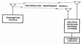
Figure 1.3 Diversity reception system
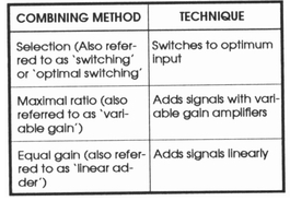
Figure 1.4 Combining method for diversity systems
Implementation of a diversity reception system can be accomplished in several ways, but all system implementations have the need to combine the received, independent signals in some method. The major drawback with any multiple reception diversity system is cost. Combining techniques are chosen based on cost and the degree of improvement required. The less predictable or less closely related the signals, the more significant the benefits of the diversity system. There are various techniques of diversity reception based on the exact method for processing and extracting the transmitted signals. Space diversity is the technique most commonly used for wireless mics. Space diversity can be implemented in many different ways, but the three basic requirements of diversity reception mentioned earlier must be satisfied. Two or more receiving antennas are required and must be at least one half wavelength apart (typically 3 feet). The amount of separation determines the degree of the uncorrelated signals. Polarization diversity is a method of space diversity in which the antennas on the receiving system are placed at angles to each other in order to capture the uncorrelated, independent signal. Each antenna provides an independent path that is selected or combined to produce the desired signal improvement. These selecting and combining methods of processing the independent signals are shown in Table 1.4
Companders
The compander was originally used to reduce static and increase the dynamic range on telephone lines. A compander is a two part system consisting of a compressor, which reduces the audio range by providing more gain to weak signals and an expander, which restores the signal to its original dynamic range ratio. The degree to which the audio energy is compressed (and subsequently expanded) is referred to as compression ratio. Typically, a wireless microphone uses a ratio of 2:1. This compression keeps loud sounds from overmodulating the transmitter and keeps quiet sounds above the hiss and static. Expansion restores the loud sounds after reception and further reduces any low-level hiss or static. Almost all FM wireless mic systems use some form of pre-emphasis and de-emphasis to reduce hiss or highfrequency noise. Basically, the high frequencies are boosted (pre-emphasized) at the mic’s transmitter and, conversely, cut (de-emphasized) at the mic’s receiver. The net result is flat audio response through the transmitter /receiver chain, but any hiss that enters the system as a result of the radio transmission is also cut by the de-emphasis. Audio companders are available with variable gain amplifiers, which respond to changing input levels. Without a compandor, a wireless mic would be more subject to noise from its transmission medium and would be unacceptable for most professional applications. Compander systems are subject to phenomena known as breathing or pumping. This soft hissing is most noticeable during low input levels. Pre-emphasis networks (similar to those used in FM) are used to further improve the transmitted signal. Although the audio compander is required for professional applications, an alternate system, called a limiter, is also available. The limiter can only prevent peak levels from becoming distorted. Hence the dynamic range, without distortion, is increased at the input by up to 40 dB, but the output remains constant with no improvement in dynamic range.
Conclusions
Today better professional wireless microphone equipment is as good as, or superior to many of the tape machines or sound systems to which the mics are connected. A wireless mic can never be better than, only as good as, a wired version of the same type. Because wireless mics are sophisticated radio systems as well as audio systems, care must be taken in setup, and a thorough understanding of the system’s parameters is advisable. Wireless systems offer many practical advantages to the user.
![]()
Microphone Pick up Patterns
Microphones are classified not only by the method of transduction but also by their pickup pattern. The pickup pattern is the way in which the element responds to sounds coming in from different directions, and there are several different standard patterns. (This is akin to the polar response of a loudspeaker… in reverse.)
Omnidirectional
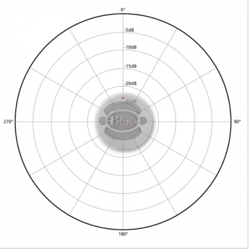
Figure 1.1 Omnidirectional polar pattern
Omnidirectional elements, as their name implies, pick up sound more-or-less equally from all directions. One might think that omnidirectional microphones are never used in sound reinforcement, since they offer no protection from feedback. This is generally the case, but not entirely so. There is a myth that cardioids are better, but omnis have better low frequency response, and less susceptibility to breath noise and wind noise. Because omnidirectional mics tend to have much smoother frequency response than directional mics, there are fewer peaks to trigger feedback, so sometimes a good omni is as useful (or more so) as a mediocre directional mic. Lavalier mics (mics worn on a lanyard around the neck, or clipped to a shirt) are often omnis. Omni mics are quite useful in recording, and virtually every studio owns at least a few of them.
Cardioid
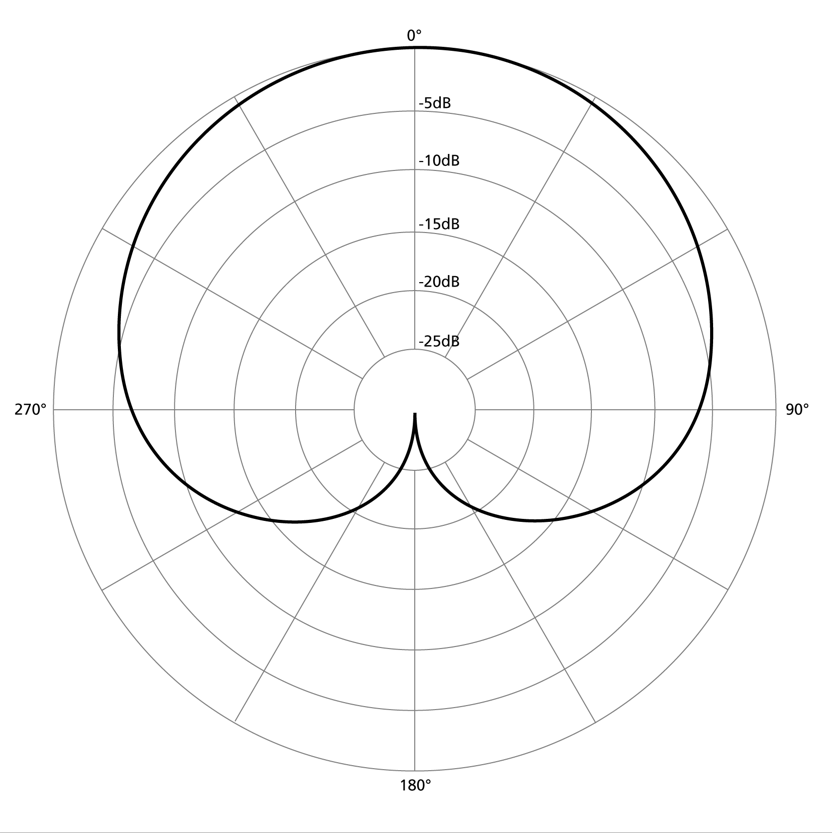
Figure 1.2 Cardioid polar pattern
The cardioid is unreservedly the most popular of all microphone pickup patterns. Figure 1.2 shows a typical cardioid polar response pattern. Note that the pattern is heart-shaped — hence the name “cardioid.” As Figure 1.2 clearly shows, the cardioid microphone is most sensitive to sounds coming in on the primary axis, and rejects sounds from the sides and rear of the microphone. The directional qualities of the cardioid make it a natural choice for sound reinforcement, since they help in reducing feedback and increasing system gain, This effect is overrated, and omnidirectional mics are often a better choice for close work than is a cardioid. Cardioids tend to have more coloration when sound does not arrive on axis because their directional qualities vary with frequency. Cardioids are quite common in recording, since they can be used to diminish unwanted sounds arriving from off-axis. Their frequency response is usually rougher than that of an omni and they are somewhat more sensitive to wind noise and breath popping.
Bidirectional or Figure 8 Polar Pattern
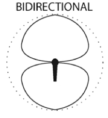
Figure 1.3 Bidirectional (Figure 8) Polar pattern
A somewhat more unusual but very useful pickup pattern is the so-called figure-8 or bidirectional. Figure 1.3 shows a typical polar response plot of a bidirectional element. The derivation of the name for this pattern is obvious from Figure 1.3 Bidirectional elements are most sensitive to sounds coming in from the front or rear of the microphone, and reject sounds from the sides. Figure-8 microphones are very useful in circumstances where pickup of two separate voices is desired — for example, in an interview situation or a barbershop quartet (where opposing singers can see each other and be picked up, but the audience is off axis and is not picked up). In recording and reinforcement, the figure-8 may be used to pick up two adjacent instruments when separate control is not desired. For example, it may be placed between two tom-toms in a drum set.
Supercardioid
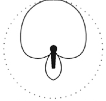
Figure 1.4 Supercardioid Polar pattern
The supercardioid is a highly directional microphone element. Figure 1.4 shows a polar response plot of a typical supercardioid microphone. Note that, in contrast to the cardioid, the supercardioid does exhibit more of a rear pickup lobe, though small. It thus supplies far less rejection of sounds coming in directly from the rear than does the cardioid. The forward pickup lobe is far more concentrated and the supercardioid offers superior rejection of sounds coming in from the sides. Supercardioids are used in special situations where greater side rejection is desired, but some rear pickup may be tolerated. Because of the concentrated forward lobe, they also may “reach” farther than a typical cardioid, and are sometimes used for pickup of distant sources. Incidentally, the supercardioid is similar to, but not identical to another very directional microphone, the hypercardioid.
Frequency Response
The frequency response of a microphone is a measure of the consistency with which it translates a given sound pressure level into a given audio signal level at different frequencies. We could say that an ideal microphone would translate a given pressure level to the same signal level no matter what the frequency (within the limits of the audio band, or 20 Hz to 20 kHz). Such a microphone would be said to have flat frequency response. While some recording microphones and many instrumentation microphones closely approach this ideal, most of the units used in professional sound work deviate from flat response — sometimes quite significantly. But frequency response variations are not necessarily bad.They are often introduced intentionally in order to produce specific performance advantages in practical applications. If you know the response of a particular microphone, you may be able to use that response to compensate for deficiencies in the quality of a sound source. At the low end, it is not uncommon for a microphone’s response to fall off below about 100 Hz, particularly in the case of vocal microphones. Since the human voice is generally incapable of producing energy that low in frequency, the effect of this limitation is to discriminate for voice frequencies, and simultaneously help to eliminate extraneous noise. For instrument amplification and recording, response to 50 Hz or below is preferred.
Many microphones exhibit a response peak in the upper frequencies. This is called a presence peak, and again is characteristic of vocal microphones. A presence peak can help to increase the intelligibility of words, so it may be a desirable characteristic. But it can also increase the possibility of feedback in sound reinforcement and is generally to be avoided in mics used for recording. It is most important, in the case of directional microphones, that the frequency response remain reasonably flat off-axis, although the sensitivity drops. Otherwise there will be a change in tonality if the person or instrument being picked up by the mic shifts off axis. Hand-held mics are most susceptible, since a slight change in the angle on which they are held will change the tonal color unless the mic has uniform frequency response off axis. Even if a mic remains in a stand, the response should be uniform off axis, or any reverberant energy will have a distorted tonal color. Uniform frequency response off axis is characteristic of good quality mics, and is one performance aspect to look for in selecting a microphone. It is probably more important than the absolute sensitivity or the actual response on axis. Remember, if the frequency response gets rough off-axis, then the quality of a voice will change as the performer moves around in front of the mic. This is hardly desirable! Frequency response variations are a major factor governing a microphone’s characteristic sound. It is important that the sound of a mic be matched to the application and the sound source, and this is best done by ear. You can get a clue from the spec sheet. For instance, a rising response with a peak in the 5 to 8 kHz range indicates the mic is probably optimized for lead vocals, some solo instruments, and for ordinary speech reinforcement. A mic with extended low frequency response and not particularly extended high frequency response would be useful for drums or other low frequency instruments. A mic with very flat response may be useful in recording, as well as in reinforcement. Since transient quality, coloration, and other factors affecting sound quality are difficult to measure with any single specification, it is difficult to provide useful guidelines for selection of a mic simply by reading the spec sheet. When in doubt, listen.
Proximity Effect
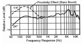
Figure 1.5 Proimity Effect diagram
Proximity effect is an increase in low-frequency response when a microphone is very close to the sound source, and is an inherent characteristic of directional microphones (omnis do not exhibit the effect). Figure 1.5 illustrates proximity effect. Proximity effect increases dramatically when the microphone is less than 2 feet away from the source, and can produce 16 dB or more of bass boost. (Actually, the overall sound level increases due to the closer proximity of the sound source to the mic, but higher frequencies are cancelled more than lower ones by the mic at this distance, so there is the equivalent of bass boost.) This can sometimes cause preamplifier overload, resulting in gross distortion. Announcers and vocalists often use proximity effect to add fullness to the sound of the voice and an experienced performer incorporates it as part of his or her mic technique. Public speakers, by contrast, are often naive about the effect, and it often destroys intelligibility in public address applications (a low cut filter is usually an effective cure in this case).
Transient Response
Transient response is a measure of a microphone’s ability to render very sharp, fast musical attacks and signal peaks. The main limitation on transient response is diaphragm mass, so condensers and ribbon mics generally exhibit better transient response than even the best dynamics. Transient response is not very important in vocal reproduction, but it attains great importance with percussive sources such as drums, piano and plucked string instruments. The transient nature of such sources is an integral part of their musical personality, so the ability to render transients accurately is highly desirable when working with them — either in reinforcement or recording. A ribbon or condenser is the best choice here. Generally speaking, the smaller a microphone, the better its transient response will be. This is because a smaller diaphragm has less mass and thus responds more quickly. The trend in recent years has been toward smaller microphones — this is due in part to the development of better electret elements — so transient response has been getting better. As a rule, you can expect modern electret units to have excellent transient characteristics.
Discussion on D.I. types and there uses
A DI unit, DI box, direct box, or simply DI (variously claimed to stand for direct input, direct injection, direct induction or direct interface), is a device typically used in recording studios to connect a high-impedance, line level, unbalanced output signal to a low-impedance microphone level balanced input, usually via XLR connector. DI’s are frequently used to connect an electric guitar or electric bass to a mixing console’s microphone input. The DI performs level matching, balancing, and either active buffering or passive impedance matching/impedance bridging to minimize noise, distortion, and ground loops.
DI boxes are extensively used with professional and semi-professional PA systems and in sound recording studios.
Passive DI Boxes
Figure 1.0 Whirlwind passive direct box
A passive DI unit typically consists of an audio transformer used as abalun. The turns ratio is typically chosen to convert a nominal 50 kΩ signal source (such as the magnetic pickup of an electric guitar) to the 100–200 Ω expected by the input of an audio mixer. Typical turns ratios are in the range of 10:1 to 20:1
Less commonly, a passive DI unit may consist of a resistive load, with or without capacitor coupling. Such units are best suited to outputs designed for headphones or loudspeakers.
The cheaper passive DI units are more susceptible to hum, and passive units tend to be less versatile than active. However, they require no batteries, are simpler to use, and the better units are extremely reliable when used as designed.
Some models have no settings, while others can have a ground liftswitch (to avoid ground loop problems), a pad switch (to accommodate different source levels) and a filter switch for coloring the sound.
Active DI Boxes
Figure 1.1 Radial active DI box
An active DI unit contains a preamplifier. Active DI units can therefore provide gain, and are inherently more complex and versatile than passive units.
Active DI units require a power source, which is normally provided by batteries or a standard AC outlet connection, and may contain the option for phantom power use.
Most active DI units provide switches to enhance their versatility. These may include gain or level adjustment, ground lift, power source selection, and mono or stereo mode. Ground lift switches often disconnect phantom power.
A pass-through connector is a second jack, sometimes simply paralleled to the input connector, that delivers the input signal unchanged, to allow the DI unit to be inserted into a signal path without interrupting it. Pass-through is also commonly referred to as a bypass. True-bypass occurs when the signal goes straight from the input jack to the output jack with no circuitry involved and no loading of the source impedance. False bypass (or simply ‘bypass’) occurs when the signal is routed through the device circuitry with buffering and no other intentional change to the signal. However, due to the nature of electrical designs there is almost always some slight change in the signal. The extent of change and how noticeable it may be can vary from unit to unit.
DI Boxes for Guitars
Figure 2.0 A fully-featured active DI box.
In live recording, the obvious use of a DI box is to create a mic-level feed from an instrument, line or speaker source that can be recorded without interfering with the original signal or risking ground-loop hum. In most cases, this simply involves using the ground lift to break the ground connection between the input and output. Note however that when recording electric guitar, and in some cases bass, the DI’d sound taken from the line output sometimes found on the back of the amplifier will require further processing using a speaker simulator before it sounds right. If used as it is, it will contain a lot of unpleasant high-frequency harmonics that would normally be removed by the limited frequency response of a typical guitar speaker. This is particularly important where any form of overdrive effect is being used.
One possible solution is to use a specialist guitar DI box that combines the usual DI box functions with a filter network that simulates the frequency response of a typical guitar loudspeaker cabinet. These are available in both active and passive versions and may either be fed a line input from a suitable preamp output, or be inserted between the amplifier output and the loudspeaker. Usually the latter option gives the most accurate result, as any coloration contributed by the power amplifier stage will also be captured.
The same applies in the studio, and while it is arguably better still to mike up a guitar where possible, sometimes this isn’t practical. In the case of bass guitars, using a DI box often produces a cleaner sound, because speaker cabinet rattles and other speaker-related problems are avoided. It’s also possible to use the high-impedance input of a DI box for recording clean guitar and bass parts. Note that acoustic guitars fitted with passive piezo electric pickups or bugs need to work into an even higher input impedance than electric guitars, so specialist preamps with very high-impedance FET input stages are recommended, rather than trying to use a regular DI box.
- Figure 2.1 Hughes & Kettner DI box with a built-in speaker simulator
Sometimes the ground-lift facility alone of the DI box can provide a solution; if you have a synth that produces an annoying hum when connected to other equipment, DI’ing it using ground lift may well get you out of trouble.
As I said at the start, DI boxes are all too easily overlooked — they’re just little boxes that solve problems (sometimes big problems), so it pays to have a couple lying around. Don’t skimp by choosing the cheapest model though, because, like any other recording component, the better-designed ones sound noticeably nicer than the very cheap ones. Try to pick a model that can handle instrument, line and speaker sources, but don’t worry about whether or not it has a transformer output unless you’re doing a lot of live recording, in which case the improved isolation of a transformer might be worth paying for. And if you do a lot of guitar work, either choose a combined DI and speaker simulator for situations in which the original speaker will still be connected, or choose a combined speaker simulator and power soak for when you want to use a valve guitar amp with no speaker.
![]()
How does Electrical Power work?
If you’re not electrically minded, think of electrical power as something easier to visualize like mechanical power. Mechanical and electrical power are very different, but both deliver power using pressure and flow, and the power delivered can be calculated by multiplying the pressure times the flow. In mechanical power, many terms are used to describe the pressure (Pounds per Square Inch, etc.) and flow (Gallons per Minute, etc.). In electric power, one term is used to describe the pressure (Voltage) and two terms are used to describe the flow (Amperes, Current).
In the earliest days, electrical power was delivered using Direct Current (DC), meaning the power flows in one direction like a water hose. Now, electrical power is delivered using Alternating Current (AC), meaning the power flow is constantly alternating directions. This change took place because electrical power can be delivered more efficiently using Alternating Current (AC) than Direct Current (DC). In the US, 60 Hertz (cycles per second) is the Alternating Current (AC) frequency. In some countries, 50 Hertz (cycles per second) is the Alternating Current (AC) frequency.
What does 1 (Single) Phase Power mean?
If you’re not electrically minded, think of 1 (Single) phase power like a one pedal bicycle where one (pushing leg) provides power.
Single Phase power refers to a two wire Alternating Current (AC) power circuit. Typically there is one power wire and one neutral wire. In the US, 120V is the standard single phase voltage with one 120V power wire and one neutral wire. In some countries, 230V is the standard single phase voltage with one 230V power wire and one neutral wire. Power flows between the power wire (through the load) and the neutral wire.
What does 2 (Dual / Split) Phase Power mean?
If you’re not electrically minded, think of 2 (Dual / Split) phase power like a two pedal bicycle where one (pushing leg) or both (pushing legs) can provide power.
Dual Phase or Split Phase power is also Single Phase because it’s a two wire Alternating Current (AC ) power circuit. In the US, this is the standard household power arrangement with two (Phase A, Phase B) 120V power wires (180 degrees out of phase with one another) like two bicycle pedals and one neutral wire. This arrangement provides (2) 120V and (1) 240V power circuits. 120V power flows (alternating) between either power wire (through the load) and the neutral wire. 240V power flows (alternating) between the two power wires (through the load).
This arrangement is used in most US households because of its flexibility. Low power loads (lights, TV, etc.) are powered using either 120V power circuit and high power loads (Water Heaters, AC Compressors) are powered using the 240V power circuit.
What does 3 (Three) Phase Power mean?
If you’re not electrically minded, think of 3 (Three) phase power like a three cylinder engine where three (pushing pistons) provide power.
Three Phase power refers to three wire Alternating Current (AC) power circuits. Typically there are three (Phase A, Phase B, Phase C) power wires (120 degrees out of phase with one another) and one neutral wire. For our purposes let’s consider a 3 Phase 4 Wire 208Y/120V power circuit. This arrangement provides (3) 120V single phase power circuits and (1) 208V three phase power circuit. 120V power flows (alternating) between any power wire (through the load) and the neutral wire. 208V power flows (alternating) between the three power wires (through the load).
Most US commercial buildings use a 3 Phase 4 Wire 208Y/120V power arrangement because of its flexibility. Low power loads (lights, computers, etc.) are powered using any 120V single phase power circuit and high power loads (Water Heaters, AC Compressors) are powered using the 208V three phase power circuit.
Most US industrial facilities use a 3 Phase 4 Wire 480Y/277V power arrangement because of its power density. Compared to single phase power circuits, three phase power circuits provide 1.732 (the square root of 3) times more power with the same current.
Using a 3 Phase power arrangement saves on electrical construction costs by reducing the current requirements, the required wire size, and the size of associated electrical devices. It also reduces energy costs because the lower current reduces the amount of electrical energy lost to resistance (converted to heat).
Color Codes
Conductors of a three-phase system are usually identified
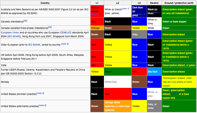
Figure 1.1 Electric wiring color codes
by a color code, to allow for balanced loading and to assure the correct phase rotation for motors. Colors used may adhere to International Standard IEC 60446 (now merged intoIEC 60445), older standards or to no standard at all and may vary even within a single installation. For example, in the U.S. and Canada, different color codes are used for grounded (earthed) and ungrounded systems.
Ohm’s Law
In numeric terms, the potential power or Voltage (expressed in Volts, V, or as E in formulas) divided by the resistance (expressed in ohms, Ω, or as R in formulas) is equal to the Amperage or current (expressed in Amps, A, or as I in formulas). The set of mathematical relationships which tie together the various characteristics of electricity is known as Ohm’s Law. They are presented here in the form of equation diagrams. To solve the equations, place your finger over the unknown variable and perform the remaining equation. For example, in the first chart, placing your finger over E (solving voltage), you would then multiply I x R; or placing your finger over I (solving current), you would then divide E by R. in Figure 1.2
![]()
Figure 1.2 Ohm’s Law Equation
![]()
Power distribution systems for live audio
Distribution Panels
Distribution panels are a convenient way to bring electricity from the venues main electric service panels that are usually located on a perimeter wall hundreds of feet away, to the sound, light and video companies set up area.
As you you will notice in Fig. 1.0 there are connections for five color coded cam lock plugs, the bottom row of receptacles are the input to the distribution panel and the top row is the pass thru, The pass thru is made to jump another distribution panel in line with first.
The Green connector is the ground, the white connector is the neutral, the black, red and blue connectors are the hot legs which carry 120 Volts each of a three phase system,
The unit also contains metering of the input and output voltage and amperage for constant monitoring by the operator as this is a very critical component for the operation of all audio gear. To little or to much voltage or amperage could cause irreversible damage to the gear and delay or stop the show!
On the front panel of the distribution or distro panel as most engineers refer to it, you will also find and assortment of 120V edison plugs along with 3- conductor twist type connectors and also powercon connectors (Power distro’s are usually custom made to the clients needs) . Each plugs voltage capacity is spread out evenly across the total output capacity of the distro, ie: if the distro’s input/ output capacity is 400 amps, then that would be the maximum load you could safely connect to it.
The panel will also have one main 400 amp breaker and each plug will also have a 20 or 30 amp circuit breaker associated with it to protect the gear connected to that particular outlet.
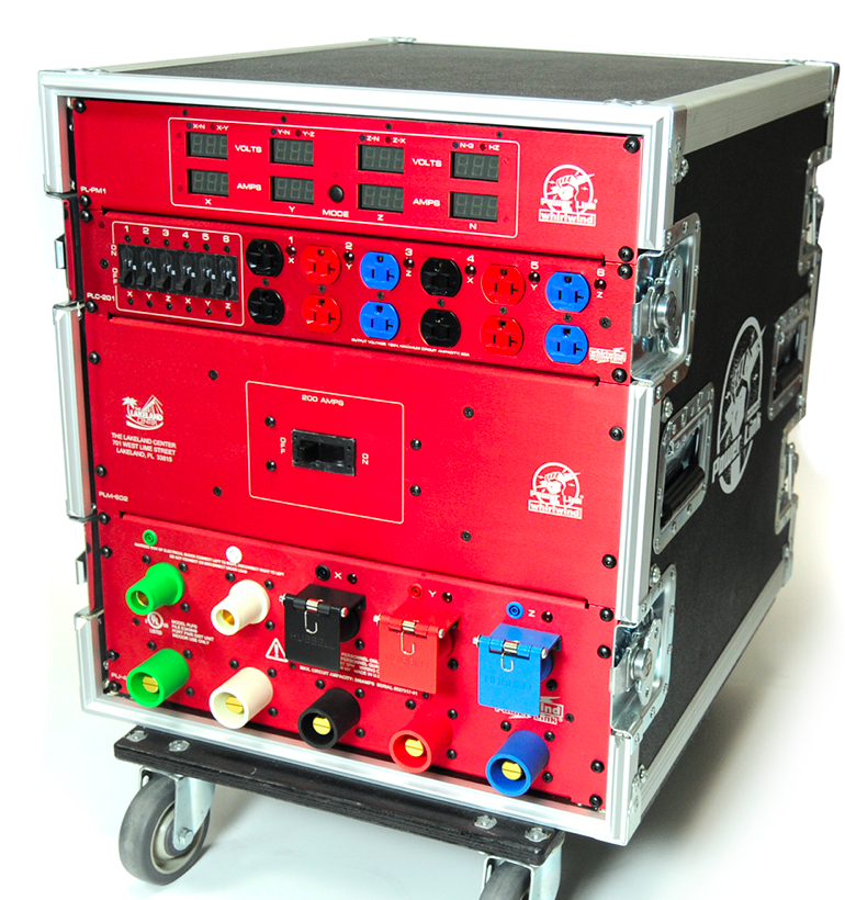
Figure 1.0 Whirlwind powerlink distro
Cam Locks
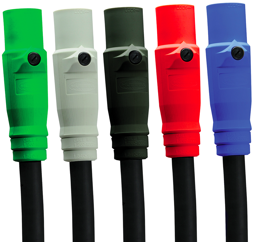
Figure 1.1 Cam Locks
Most high-power feeder wires use these single-conductor, insert-and-twist connectors for 8-gauge wire and larger feeders.
Cam Lock connectors come in three sizes (1015, 1016 and 1017).
The 1016 size is the most common with a maximum rating of 400 amperes. The 1015-size Cam Locks are typically dubbed mini-cams for 8- to 4-gauge wire and a maximum rating of 150 amperes. I rarely see mini-cams in use, usually with stage lighting dimmer racks and some touring power amp racks. Even rarer are the 1017 maxi-cams with 350 to 750 mcm feeders and a maximum rating of 690 amperes. The usual 1016 Cam Locks can handle #2 to 4-0 feeder wire.
Most Cam Locks are weatherproof, with their colored rubber boots protecting innocent fingers when open and forming a watertight connection when connected. Cam Locks also come in panel-mount as well as cable connectors. When dealing with Cam Lock feeders (carney cable) and Cam Locks, it is best to let a trained person with the right fixtures and jigs do the connector to feeder attachment to ensure a tight seal on the boot to the cable jacket.
Straight-Blade Plugs and Receptacles
Of the lower amperage connectors, the straight-blade dryer and electric range plugs win the popularity contest due to lowest cost and availability. Yeah, many touring racks have 30- and 50-ampere twist-lock power interconnects, but there is almost $100 of brass and nylon involved in each pair of plug and receptacle.
Of course, not all receptacles are wired 100% correctly. That is why you should have a working knowledge of the commonly- encountered receptacles and know which slots are supposed to be hot, and which are to be neutrals and grounds. And do not leave it at metering the 120 volts to neutral, but check for no voltage between the safety ground and neutral contacts; then check the resistance between safety ground and neutral for decent continuity.
Everyone should be familiar with the NEMA 5-15 household “Edison” plugs and receptacles. But the most common good distro plugs and receptacles are the four-contact NEMA 14-30 dryer and NEMA 14-50 range devices. The older NEMA 10-30 dryer and 10-50 range connector with the three-prongs (hot-hot-ground), were intended for the older 240 VAC-only appliances and grandfathered out of usage back in the 1980s.
Tails
Distro tails are typical moderately short pieces of feeder cabling that have a receptacle (female connector) at one end, and 6 inches to a foot of loose conductors at the other end. I have 10 to 15 feet tails for both my Cam Lock feeders (2-gauge) and my 14-50 feeders (6-gauge). Most tails shrink with usage as the loose ends are bared a half-inch for screw termination into bull switches, circuit breakers or ground or neutral buss-bars. Be wise and always de- energize your hots before connecting the tail bare ends to the screw orifices. As your bare stranded copper wire ends fray with usage, trim back the frays and strip new ends. And as I have to state, if you are not a licensed electrician, do not play with tails or the legal professionals may lay waste to your financial health for the foreseeable future. While most moderate to bigger clubs do provide distro receptacles, some may only have bull switch/sub-panel breakouts available.
![]()
![]()
Preparing your sound system
This part of the process is the most important part before you head out to that very important event!
Check List:
Mixing Consoles check list:
1. Mic preamps
2. Channel faders
3. Aux. sends
4. Equalizers
5. Input and output connections including insert points.
Equipment racks check list:
1. Racks are labeled and cabled
2. All inter connections are checked
3. All inter connected gear is level matched and aligned.
Mic cable/Microphone/DI check list:
1. Test all dynamic mics for functionality
2. Test all condensor mics for functionality and phantom power connectivity.
3. Test all direct boxes for functionality and phantom power connectivity.
4. Test all mic cables for functionality and phase
Speaker system check list:
1. Check individual speaker cabinets to make sure all components are working and in phase.
2. Check all speaker cables to make sure they are working correctly and in phase.
3. Check all amplifiers for functionality and clean fan filters
Rigging:
1. Check all rigging motors for functionality
2. Check all rigging motor chains for bad links and or kinks
3. Check all rigging motor power distros for functionality
4. Check all rigging motor power cables for correct polarity/phase wiring
Power distribution system:
1. Check all power distro breakers and disconnects for functionality
2. Check all power distro cam lock cables
3. Check all power distro equipment inter connect cables
4. Check all stage/band power quad boxes and extension cables
Labeling:
1. Label/color code all equipment rack panels (for fast & sure connections)
2. Label/color code all cables & cable cases (for correct cable usage)
3. Label/color code all equipment rack cases (for proper stage or audience placement)
4. Label/color code all speaker cabinets (for proper stacking or flying positioning)
All of the above will facilitate sitting up and breaking down your system more efficiently, and you’ll be less likely to forget or lose any gear or cables.
![]()
Flying or ground stacking the sound system
Some in audio think that the term “rigging” only applies when loudspeakers are flown, but it also pertains to lesser endeavors such as placing a single loudspeaker on a tripod stand. The bottom line is that for any piece of production gear not sitting directly on the ground, steps must be in place to insure that it does not fall and injure someone (or worse).
The Occupational Safety and Health Administration (OSHA), the U.S. agency that sets and enforces work safety standards, states a company must have “competent” and “qualified” persons in charge of rigging. A competent person is described as one who is capable of identifying existing and predictable hazards in the surroundings, which are dangerous to employees and has authority to take prompt corrective measures to eliminate them.
Meanwhile, a qualified person is defined as one who by possession of a recognized degree, certificate or by extensive knowledge, training and experience, has successfully demonstrated the ability to solve problems relating to the subject matter and the project. Therefore, a qualified person designs a rigging system, and a competent person installs and monitors the rig, and inspects its components.
While OSHA rules and standards are mainly focused toward rigging in the construction industry and are geared toward safety of employees, we also need to look after the safety of performers and members of the public who attend events. Not everyone at a gig may be at the level of a qualified or competent person, but all should focused on safety. Anyone on a production crew who sees a problem with rigging (or any other safety issue, for that matter) can call “stop” and point out the issue so it can be addressed and corrected to avoid an accident or injury.
Good places to look for training and information are manufacturers who make rigging equipment or loudspeakers that fly. They provide specific safety and operating instructions for their own gear. Two organizations focused on entertainment rigging training are the ESTA Foundation (estafoundation.org) and PLASA, which offers the ETCP rigging certification program (etcp.plasa.org) for entertainment riggers who work in theaters or arenas.
There are also several independent rigging schools and manufacturers that offer training and certification programs as well. A good reference book is Entertainment Rigging by Harry Donovan. While reading about proper rigging practices is highly recommended, it’s not the same as getting hands-on training. Experience along with knowledge is required for a person to be designated as competent.
In most rigging situations there are at least two riggers on site, one of them will be the “up rigger” and the other will be the “down rigger”
The up riggers job is to climb up on the supporting beams of the venue structure and precisely position, hang and secure the steel ropes that attache to the chain rigging motors.
The down riggers job is to spot the up rigger from below to make sure he is placing his rigging point in the correct place on the beam and to feed him up all of the associated rigging hardware.
The Essentials
Before we talking about specific rigging approaches, let’s look at a few terms. Initials often seen on stands and rigging equipment are “WLL” (Working Load Limit), “SWL” (Safe Working Load), or “MRL” (Maximum Rated Load). For practical purposes, they mean basically the same thing: the maximum amount of static weight that the item will safely hold continuously, when it is used correctly as intended. The key here is a static load, or a load that does not move. Any movement like loudspeakers swinging in the wind or even the act of raising or lowering a chain motor puts additional stresses on rigging equipment. Safe working load limits should never be exceeded.
Another term to be familiar with is “Safety Factor,” the margin of safety added to an item that takes into account loadings over and above the weight being hoisted and for reductions in capacity due to the extra loads imposed by acceleration and inertia (movement).
Some European countries have mandated 10:1 safety margins, while those in the U.S. are still largely self-enforced. Many production companies in the U.S. have adopted a 7:1 safety factor, with margins for life safety (fall arrest, performer aerial acts, etc.) using a 10:1 ratio.
In short, an item’s safe working load is derived by dividing the breaking strength (the point of failure) by the safety factor. An example would be a shackle with a breaking strength of 7 tons would have a safe working load of 1 ton here in the U.S. (SWL= Breaking Strength (7 tons)/safety factor (7:1).
System design plays a large part in the rating of individual components. Like a chain, a rigging system is only as strong as its weakest link. Pull angles and side loadings de-rate the SWL of many items including eye bolts and shackles.
The splay angle of bridles (two or more legs of wire attached to a ring that spreads the load across a larger area) affects their weight loading. Spansets and wire rope slings will have different capacities based on their positioning (i.e., straight vertical pull versus a basket configuration).
All of these factors need to be taken into account by a qualified person who will design the rigging system.
In addition, a competent person should inspect all rigging equipment and hardware before use and periodically do a major inspection for signs of wear, abuse and general adequacy, as well as perform any manufacturer recommended preventive maintenance.
Follow the rules and don’t cut corners when it comes to rigging. Use only loudspeaker cabinets designed by the manufacturer to fly, and use only hardware approved for that specific model. Follow all manufacturer recommendations concerning their individual products. Never modify any rigging hardware as it may affect the weight loading capacity of the item. Purchase only known quality rigging equipment.
Further, factor in enough time to do rigging correctly and make sure the crew isn’t tired—rushing and fatigue cause accidents. Double check everything before it goes up in the air. Once items leave the ground, they better be rigged properly or gravity will demonstrate why it’s the most powerful force in the universe!
Only finger tighten shackle bolts, never use a tool. If you’re worried that a pin might vibrate out, mouse (secure) the pin in place with twine or wire. Always load a shackle pin to end, never from side to side. When attaching to a beam or other structural component, always pad the beam edges so a sharp edge doesn’t injure the wire rope or sling. Never leave any slack in guide wires.
Plenty Of Methods
Now let’s move on to looking at ways loudspeakers can be deployed and positioned.
Ground Stacking
The easiest way to set up a PA is by placing it on the ground or stage. While this method seems to have no dangers associated with it, there are a few lurking. Loudspeakers stacked on top on each other can fall from the stack due to vibrations. Truck straps are commonly employed to keep them from vibrating apart.
Keep in mind, however, that strapped stacks can be top heavy and can topple over, either from vibrations or from a crowd pushing to get closer to the stage. Using a larger subwoofer that provides a bigger footprint as the base of a stack can add stability to a strapped stack of loudspeakers.
Many line arrays are designed to be ground stacked by inverting the fly bar and using it as a base. The cabinets are connected to each other and the base with their fly hardware, making a stable ground stack with the angles being able to be adjusted for coverage same as when flown. Loudspeakers placed on uneven terrain will be unstable and if used on a grass or dirt surface could shift during rain. A common remedy is to place a stage or plywood platform on the ground and level it. Then the loudspeaker stack will have a solid level surface to rest upon and not sink into mud after a rain storm.
Scaffolding
Before flying PA was common practice, stacking loudspeaker boxes on scaffolding towers was a common approach at larger shows. It’s still a common way of elevating horizontal arrays and delay stacks at festivals and fairs. On uneven ground, screw jack leveling legs should be used to ensure the scaffolding is level and all cross and diagonal bracing needs to be in place before loading the tower. Make sure all decking is securely in place before any speakers placed on the tower and they should be strapped down so they can’t vibrate off.
If used outdoors, the tower needs to be guyed down in case of winds. Signage and banners placed on the scaffolding act like sails and will transmit high wind loading to the system. Using an open weave fabric for the signage will allow some wind the blow through, reducing the wind loading on the tower.
Banners should have a quick release system in place so they can be removed rapidly in case of unexpected high winds. Line arrays can be flown inside scaffolding towers, with the chain motor for the array usually connected to a beam secured across the top of the tower. Make sure the beam is secured to the tower and not just held in place by the weight of the PA.
Stands
Tripod stands are commonly employed for loudspeakers at smaller shows. While very safe, the tripod legs should be extended to their largest footprint when possible so they provide maximum stability for the stand. Make sure the top of the stand is correctly sized for the loudspeaker socket or the cabinet could tilt and its center of gravity will not be directly over the pole.
Also, position the stand where the tripod legs will not be a trip hazard as a fall could cause a person injury, as well as possibly knock over the stand (and loudspeaker).
Use fixed leg tripod stands only on level ground. Saddle style sandbags can be used with tripod stands to add a bit of weight to the bottom for increased stability. The sandbag should straddle the leg, not hang from any bracing. To avoid crew injury, larger loudspeakers should be hoisted onto stands by two people.
Truss Totem
Particularly popular on corporate gigs, truss sections are bolted to bases and used in an upright position for lighting trees, projector and delay speaker stands. Totems can be very top heavy so additional weight, usually sandbags, are placed on the base to help with stability.
When used with a single loudspeaker on the top, make sure that the cabinet’s center of gravity is located directly over the center of the truss. When used with a column-type loudspeaker attached to the side of the truss, make sure that additional weight is placed on the base on the opposite side to offset any leaning tendency caused by the side loading of the loudspeaker. Totems should only be used on level ground. If used outdoors, these systems need to be guided down.
Pole Mounted On Sub
Pole mounting a loudspeaker on a subwoofer provides a clean and easy setup for many gigs. It allows the top cabinet to be raised to a good operating height while eliminating the tripod base that may become a trip hazard. Some systems allow for the use of two poles for larger top cabinets or line array-style boxes. To avoid problems, use only the manufacturer’s recommended poles with these systems, as different poles may not be compatible or as stable as the factory units.
Crank Towers
These come in many forms from larger versions of tripods to heavy-duty units that can hold 600-plus pounds. Crank towers are becoming a popular option to fly a smaller array without having to use motors. Make sure that all outriggers and legs are extended and the tower is leveled correctly before raising the load. Factor in the rigging hardware weight and speaker cable weight when figuring out the total weight you will be lifting. Check with the manufacturer before using the lift outdoors and follow their recommendations on using the system outside.
Pair Of Towers & Truss
This is a common setup at medium-sized shows and corporates that utilizes a pair of crank towers and a span of truss that goes across the front of the stage. The truss usually does double duty and supports some front stage wash lights as well as the loudspeakers. It can give the ability to provide a small left, center and right array without requiring any ceiling points.
Care should be taken to not overload the systems, because total working load on horizontal truss is based on an evenly distributed load. Also take into consideration the weight of the loudspeaker and lighting cables when figuring out the total weight of the system. This type of setup is considered a system and needs to be designed by a qualified rigger.
Line Array Tower Truss
A relatively new option for positioning loudspeakers is the line array tower. Made from truss sections and specialty hardware fittings, these systems can be disassembled for transport or storage and easily bolted together on the job site to support a wide variety of speaker arrays.
Smaller towers may use a manual hoist to lift the array, while larger units utilize a powered hoist. Make sure the tower is leveled correctly before use. When deployed outdoors, the tower must be guyed down per the manufacturer’s recommendation. Some tower systems allow placing subwoofers on top of the forward outrigger legs so they can act as additional ballast.
Dead Hang Flown
Dead hang means that an item is connected to a support structure without a motor or lift system. The attachment point can be an exposed ceiling beam, tent pole, section of truss, etc. An engineer should be called in to certify the weight loading ability of any ceiling point before use if it is not known.
Only competent or qualified riggers should dead hang cabinets as each hanging point needs to be individually assessed by a person with knowledge and experience to determine what hardware is required to safely support and position the loudspeakers.
Access to dead hang points may involve a personnel lift. Make sure fall protection systems are used by anybody in the lift and that the systems are inspected before use. A spotter may be required to assist the lift operator as many types of equipment have blind spots.
Air Wall Tracks
Air walls are the moveable walls in large meeting spaces and ballrooms. These tracks are often utilized as ceiling points for video screens, lighting and audio delay speakers when they are not being used by the wall sections. While technically considered a dead hang, air walls pose a few specific challenges to production crews. All air walls are not the same, and each requires specific fittings dedicated for that track style.
There are also a few universal type air wall hangers that will fit a wide variety of common track styles—but they don’t fit all. Be sure to use the correct fitting or hanger for the track because some models may seem to fit into the wrong tracks, but they’re not providing the correct support. Air walls have limited weight bearing capacity per point, so it’s critical not to overload any point on the track. Because of their limited single point capacities, air walls are commonly limited to flying lightweight objects, or used as cable supports.
A building’s engineering department should be able to tell you how much weight and at what intervals you can fly from the track. One important thing to consider is whether the room needs to be reconfigured and the walls moved during or immediately after the event. If the walls need the tracks, nothing else can be installed on them.
Unistrut Tracks
It’s very common for convention centers and newer hotel ballrooms to have Unistrut tracks installed in ceilings and sometimes even walls. Like air walls, they require a specific connector to be safely used. Different sized tracks have different safe working loads. Again, a building’s engineering department should be able to tell you the weight limits and spacing required for utilizing the tracks.
Motors
They can be used singly to hoist individual loudspeakers and small arrays, and in multiples to hoist larger arrays. A motor attached to the rear of an array can be used to help tilt and aim the array. Only competent or qualified persons should perform any rigging with motors.
Before use, check the motor hooks and inspect the chain for any signs of damage. Make sure the chain bag is attached correctly and is in good shape. Before any motor is operated, the rigger needs to make sure that everybody on the deck is aware that something will be moving. Before an array or truss is lifted, one competent person should double check all rigging hardware and fittings.
Construction Lifts
They’re sometimes used to elevate or fly loudspeakers at festivals. Scissor lifts are popular when small horizontal arrays need to be raised, moved or relocated at events like airshows. Larger festivals might utilize construction cranes or large extendable boom forklifts to fly the main PA system.
Make sure the equipment operators are certified on that model unit, and that an operator is monitoring the equipment continuously during use. Weight loading changes depending on the angle of the boom so it’s vital to no overload the equipment during use. Tag lines should be used to keep an array from swinging in the wind. An engineer should determine the maximum wind speeds the systems can operate in, and if the wind reaches that limit, the PA should be lowered immediately to the ground.
Remember, safety is the most important thing. Rigging is dangerous, but using the proper equipment and procedures, skilled people can overcome gravity, one loudspeaker at a time.
![]()
Speaker system component balancing and equalizing the venue
Nowadays computer simulations often support the design and the engineering of rooms and buildings. In acoustics, this option became feasible in the 1990s. Before that time the acoustic design had to be based on fundamental equations which deliver a trend and information about the sound field average. Usually this involved a calculation of the reverberation time or sound transmission coefficients in order to proof the design concept and its match with the desired building performance. The acoustic component is obviously relevant for speech communication, for music perception and for the purpose of noise control. The human perception, however, is sensitive to specific features of the sound source (e.g., directional characteristics), the source signal and the sound propagation in the room or building. These features are often not sufficiently described by averages of acoustic data such as reverberation times and sound pressure levels and require more detailed investigations.
Reverberation is considered to be an extremely important phenomenon in room acoustics. It generally varies for different sound frequencies. A typical value for an auditorium (e.g., a lecture hall with a volume of 800 m3) is a reverberation time of one second, with a slight increase towards bass frequencies and a decrease towards treble. It can be predicted rather precisely by using the room volume and the average absorption. Other criteria, however, which describe more specifically the spatial impression, the clarity of speech, and the sensation of distance to the source cannot be predicted accurately with a similarly basic approach, and should rather be derived from the room impulse response.
In a geometrical model, the sound travels on straight lines and loses energy due to absorption whenever a wall reflection occurs. The part on the right hand side of Figure 1 illustrates the reflection paths of the impulsive sound ray in the room, the left hand side shows the corresponding function of energy vs. time, usually called energy impulse response of the room.
Figure 1. Simplified example of an energy impulse response of a room, including direct sound, early reflections and late reverberation.
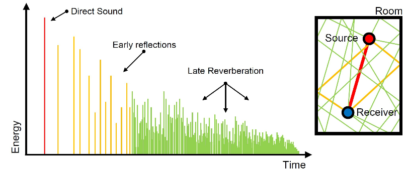
Relevant information about the acoustic quality of a room can be derived from the impulse response. Some perceptual criteria such as reverberance, clarity of spaciousness can be obtained from post-processing of the impulse response, so that more numbers are available to analyze the acoustic quality in detail.
More detailed programs like “ease focus” invented by Ahnert Feistel Media Group. Located in Berlin, Germany have come into play, it analyzes the venue and aims the speaker system to cover the seated areas only which minimizes the sound from hitting the walls and ceilings. (K-array utilizes this software also)
All of the above computer assisted programs and technics are great tools to assist you in mathematically equalizing your venue, but the ultimate test to making sure your speaker system is intelligible for voice and music is to take a commonly used microphone (Shure Beta 58) and talk naturally and clearly into the system, then use your parametric or graphic equalizer to remove or even out the frequencies that are abstrusive or to loud in the venue.
The human voice, acoustic instruments and or electrified instruments will energize the seating space of a venue quite differently than using test tones such as pink noise or sine waves.
![]()
![]()
Small club, theater and large arena mixing techniques- in progress…
![]()
Mixing vocals, drums, percussion’s, horns, guitars, acoustic piano and large orchestra’s for live performance- in progress..
![]()
![]()
Equalizing monitor wedges and side fill speakers- in progress…..
![]()
Monitor wedge mixing- in progress…
![]()
![]()
Making input list and stage plots- in progress…
![]()
Setting and patching up the band and vocal mics- in progress….
![]()
Sound checking the band- in progress…
![]()
Mixing the show!- in progress…
![]()
![]()
Parametric equalizers & Hi/Low pass filters
Most professional mixing consoles have 4-band equalization on each input. Two of the equalization controls have sweepable center frequencies. More elaborate mixing consoles have 4 or 5 band fully parametric equalization with variable center frequency, filter Q and EQ. gain control knobs in each frequency band.
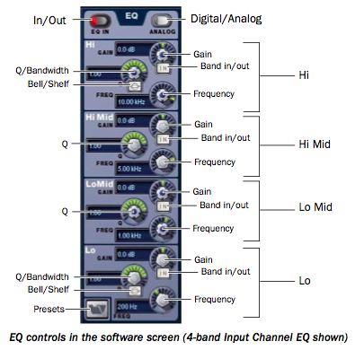
Venue parametric EQ. gui.
In more expensive consoles the equalizer section will contain the Hi/low pass filters, the job of the hi pass filter is to decrease in either fixed or variable per octave steps the low frequency content of the input signal.
The job of the low pass filter is to decrease in either fixed or variable per octave steps the hi frequency content of the input signal.
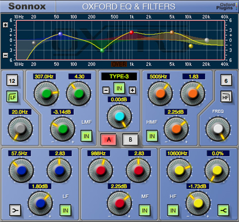
Sonnox Oxford Parametric EQ-Plug-in
The purpose of input channel equalization and filters is to enhance the response of an individual source. For example, input equalization can mellow the sound of a nasal singer’s voice, reduce the resonance picked up from a bass guitar speaker or add sparkle to a cymbal. Note that the entire equalization section can be bypassed with a switch.
![]()
Aux. effects sends or Monitor mix sends
All analog mixing consoles have anywhere from 4 to 48 auxiliary buses which receive their signals from each input channel pre or post fader and EQ. through individual volume controls. The aux buses constitute a separate mixing system that can be used for many different purposes, including a stage monitor wedge mix, side-fill mix, In Ear mix or feeds to outboard special effects processors, or a broadcast mix minus feed to a Tv broadcast truck.
All digital mixers have the same possible amount of Aux. sends, but they can also send to on-board reverb, delay, chorus and many, many other effects for the engineer to pick from.

The affected signal can be returned through an effects return input, an auxiliary input, or even through another input channel. Regardless of the return input chosen, the affected signal needs to be mixed with the original signal.
![]()
Console insert points/ Patching in outboard gear
The input channel insert point allows the operator to connect an external effects or signal processing device like an equalizer, reverberation unit, compressor or noise gate. Applying the device at this point in the signal chain affects only that input source, not the entire program. Thus, the operator can add reverberation to a lead singer’s voice without affecting the backup vocals or other instruments connected to the mixer.
On the more expensive consoles the engineer is given a choice of placing the insert signal pre or post the equalizer section.

Venue channel input diagram
![]()
Console Automation and Snapshots
In live theater, a scene is an identifiable part of a play in which the setting doesn’t change and action flows relatively smoothly for a period of time. A scene/snapshot on a mixing console is a group of settings chosen to support a scene in a play. The same concept could be applied to a concert, where one scene/snapshot could be a set of fast song(s) with the entire backup band in action, and another scene/snapshot could be a set of slow song(s) with only the lead singer and a few instrumentalists.
Some larger mixing consoles have the ability to store and recall such scenes/snapshots, that is, they can store and recall selected settings, including faders, auxes, equalization., mic preamp, input/output channel muting and VCA group settings.
The operator sets up a scene/snapshot during rehearsal and recalls it at the appropriate time during the performance. In the hands of an experienced operator, this is an extremely powerful feature that is much like having a group of separate mixing consoles , each one preset to a scene or snapshot, and switching among them as needed.
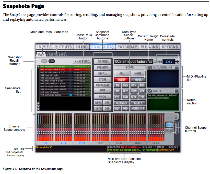
Venue Snapshot/Automation controls
The more elaborate consoles can be automated via timecode to trigger those same scene/snapshots at a specific timecode, thus allowing the engineer to focus in more intently on mixing rather than remembering to change his snapshots for every scene.
Timecode driven automation is usually used in very large theater or live concert settings were not only the audio changes are being triggered but also lighting, pyrotechnics and staging pieces are being changed or moved to fit a specific scene, such as a Cirque du soleil show.
![]()
VCA/DCA and analog Sub Groups
VCA or DCA stands for “voltage controlled or digitally controlled amplifier.
This section on the digital and or analog mixing console provides a means of grouping multiple input channels together to control there volumes with one or multiple VCA/DCA group faders.(ie: all of the drum channels or all of the background vocal channels)
The VCA/DCA group fader uses a control voltage to increase or decrease the volume of all the input channels that are assigned to it, but it does not pass the actual audio from the fader to its input, the actual audio signal goes thru the pan pot and to the stereo bus fader to be heard on the speaker system.
If you have an effect being sent from any of those channels, the gain to the post fade send will also increase or decrease, which will make the effect get louder or softer in per portion with the dry signal of the channel fader.

Venue outputs page
The Analog subgroup although much like the VCA/DCA subgroups, acts in a bit different manner, the actual audio goes from the channel fader to the analog subgroup fader, and the subgroup fader passes the audio to the stereo bus outputs.
In this grouping scenario if you have an effect send being used and the volume of the analog subgroup is increased or decreased, those increases or decreases will not make the effect send level on those input channels go up or down because the channel fader level is not physically moving, its just passing it’s audio at a static level onto the analog subgroup, and the subgroups output level is increasing or deceasing.
Note:
Your effect will either get to loud because the subgroup fader level was decreased and the dry to wet ratio has been changed, or it will not be heard because the subgroup level has been increased.
![]()
![]()
![]()
Audio terms
Console, Mixing Console, Audio Mixer, Sound board
Stage box, input box, mic input box
Mic splitter, splitter box, splitter
Microphone, mic
Mic preamp, preamp
Condenser mic, dynamic mic, tube mic, ribbon mic
Equalizer, EQ.
Parametric EQ., semi parametric EQ., dynamic EQ.
Noise gates, gates
Compressor, comps.
Vca groups, Dca groups, analog groups, sub groups
Cardiod, hyper cardiod, unidirectional, omni directional, figure eight
XLR cable, 1/4″ cable, trs cable, speakon cable, TT cable, multi pair cable
Patchbay, patch panel, jack field
Phase meter, Correlation meter
Cue, PFL, Solo
Audio Brands & Manufacturers
A
Avalon design
Adams speakers
Avid (pro tools)
Antares (auto tune)
Akg microphones
Api consoles
Apple computers
Aphex
Anvil cases
Ampeg
Aviom
B
Bgw
Belden
Bss
C
Calrec consoles
Canare
Calzone cases
D
Dbx
Drawmer electronics
Digico
D & B
Dyn audio
E
Euphonics consoles
Echo farm
Electro voice
F
Focusrite
G
Genelec
Grace
H
Heil microphones
Harmon kardin
I
ISP technologies
J
JBL
K
Krk
![]()
Audio Brands & Manufacturers cont.
L
L’acoustics
M
Midas
Melodyne
M-audio
Millennia
N
Neve
Nuetric
P
Powersoft
Peavey electronics
Paragon
R
Rupert Neve Designs
Radial
Rocnet
Royer
S
Solid State Logic
Sony Electronics
Sonnox Ltd.
Shure Inc.
Sennheiser Electronic Corp.
Soundcraft-Studer Corp.
Schoeps Microphones
Samson Technologies
SKB Corp.
T
TC Electronics
U
Ultimate Ears
Universal Audio
V
Vue Audiotechnik
W
Waves Inc.
Whirlwind
X
Xilica Audio Design
Y
Yamaha
Yorkville Sound
Z
Zoom
MML Audio Dictionary A-Z

SSL L500 Digital mixing console
![]()
![]()
The client is always right!
The most important lesson to be learned in the music business is, it is a BUSINESS!! and “The Client is always right” EVEN WHEN THERE DEAD WRONG!
The music business is mostly built on individuals EGO’s!!, and those ego’s are very fragile, If you rub an artist, artist manager, personal assistant, valet, water boy or even the bus boy the wrong way you may lose your gig and never find out why.
The only thing you know is, you got a phone call from whom ever is in charge and a plane ticket home!!
You never know who may have the artist ear!
They could have absolutely nothing to do with what your job is, but everything to do with weather you keep your job.
Instructor short stories:
Earth, Wind & Fire and the lead singer with no back bone
Chris Brown and the mom with no back bone
Beyonce and the scheming tour manager
Gladys Knight and the travel agent
![]()
The Psychology of mixing a Superstar..
Being a great audio engineer goes far beyond knowing how to operate all of the gear and getting a great sound!
After gaining all of the technical knowledge and working your way up from small club gigs to finally arriving at that major Pop/Rock star gig you’ve been dreaming of, your going to be faced with the super star “DIVA” (Divas can be male or female).
They think the world revolves around them and you should bow before them in their presence.
WELL, This is were you must put down your engineers hat and pick up your politicians hat, you must figure out very quickly what this DIVA is all about, what kind of people they like and hang out with, what turns them on and off!
Most Divas have a false since of reality and that’s probably what got them to the super star level in the first place (Thinking they were a super star before it actually happened!), It takes a very special person and personality to be out front leading the group, band or even worst, being a solo artist.
To make the situation even worst, the record companies promotional machine hypes this person or group’s ego’s into orbit with all of the magazine ads, Tv shows, commercials, private parties, bling bling jewlery, rented lear jets, Rolls Royces and yachts.
They surround the artist with all these things and put it in there over the top videos, and this does only one thing, FEED THERE EGO even more!!!
So, when you arrive at the top be ready for all of the above and maybe a little more.
To successfully navigate the entertainment business world you have to have what i refer to as the “Randy (American Idol) Jackson” swagger, he’s figured out how to make people feel good about themselves even when they suck or when the situation is bad, he diffuses it.
You must be transparent as possible and never ever try to become there new BFF, that only leads to disappointment when they get tired of you, and they will because you’re not on there level, the artist are taught by there record companies and management that all crew and band members are expendable!!, because they never want anyone to get or be closer to the artist than them (that’s there way of staying in control)
You must make the artist feel like you’re totally in control of there sound at all times and under all conditions, (never let them see you sweat) If you draw to much attention to yourself or your position, one day when things just aren’t happening sound wise, someone will say to the artist, he isn’t that good and he’s always >>>>>>
That one day/ situation gets the artist to thinking that you may not be all that!!, or you’re a trouble maker like his or her friend said, and next thing you know, you get that phone call or even worst, an e-mail!
The music business can be very unforgiving, so as a rule, when you have a gig, keep looking for the next ONE!!
Instructor short story:
Kelly Clarkson’s manager
![]()
“Long Hours!, Short Money! & the Love of Music!”
Surviving in the audio world of either the music or Tv business takes talent, people skills and the biggest one of all, NETWORKING SKILLS!!
At the beginning of your career you must be prepared and willing to work long hours either interning for free or being paid very little, you’ll be doing the grunt work like pulling heavy snake cable and A/C cable, loading and unloading trucks or working in the shop doing QC (quality control) work, that’s basically checking out the gear when it comes back in from a show to make sure it’s still in good working condition before it goes out on the next show.
The main thing to remember while in this phase of your career is to watch and absorb all of the different audio jobs going on in the shop and on the gig, you never know what you’ll be called on to do, you may have to fill in for the guy that flies the main speaker system or mix front of house (FOH) because someone got fired and you were the only one available.
“Remember, everyone has that special story of how they got into the business”
As your responsibilities increase so will your money!, But until then you must love the music or whatever it is that’s turning you on about being in this business!
Instructor short story:
Networking your way to top of the stack!
![]()
“For the Love of Music, Not Money!”- in progress….
![]()
Touring, Life on the Road!
If you choose to be a touring engineer you must be prepared to take long road trips, sleep in strange hotel beds and ride for months at a time on a tour bus, and sleeping in a 6-foot long by 3-foot wide bunk.
You’ll be working and living with people some of which you won’t know and possibly even having to share a hotel room with one of them on your days off. (Sharing a room is very old school thinking these days)
Working on a touring road crew everyone has very specific jobs to do because there’s usually only 4 to 6 audio personal assigned to a tour, your day on the typical theater or arena tour will consist of breakfast at 8am, load-in at 9am.
The first thing that will happen while loading in all of your audio gear is the person(s) in your crew that is responsible for flying the speaker system will confer with the rigging team on were they would like to place there points (speaker rigging points) to properly hang there speakers so they will cover the designated venue seating for that nights performance.(The FOH engineer is usually involved in this process also)
The second thing that will happen is the person who’s job it is to prepare the electrical power will confer with the venue electrician to tie in the sound companies electrical distribution panel, at this point all of the A/C cable and audio snakes to the front of house (FOH) and monitor positions are being laid out, this process if you are in a union run venue is done by the local union stage hands which are being directed by someone on the sound crew.
Fast forward about 3 or 4 hours and the mixing consoles, lighting, staging and band gear are all set and tested and you’re awaiting the band and artist to show up for their sound check/rehearsal.
Instructor short stories:
On tour with Earth, Wind & Fire, Beyonce & Jennifer Lopez
![]()
![]()
Equipment Relationships- In Progress…
All pieces of audio gear have relationships with other pieces of audio gear and are usually hooked together by some sort of audio cable, such as an “XLR” cable Speakon cable, or an “1/4” cable.
In this chapter you will learn how the primary pieces of audio gear are connected to one another, which is referred to as “signal flow”, and how to do basic trouble shooting techniques to find bad cable connections or mis-patched lines in the audio chain.

Live sound system flow chart
Signal Flow
The mixing console is were most connections are either received from or sent to other pieces of audio gear.
That audio gear will consist of but not limited to the following pieces:
Microphones & Instruments:
Wired microphones and wireless microphones, Keyboards, Guitars, Drums .
Non live sources:
Pro Tools (DAW) software, CD Players, Record Turntables, Audio Tape Decks, Video Tape Decks, Instant Replay units
Signal Processing:
Parametric and graphic Equalizers, Digital delays, Reverb units, Electronic crossover networks, Compressors and limiters, Noise gates.
Power amplifiers:
Digital DSP amplifiers, Analog amplifiers
Loudspeakers:
Line array speaker system, beam steerable speaker systems, separate component loudspeakers, Boxed loudspeaker systems, Powered loudspeaker systems, Loudspeaker arrays, Stage monitor loudspeakers.

Sound system signal flow chart
The typical sound system output signal flow would be from the mixing console stereo output to the speaker system crossover inputs, from the crossover outputs to the speaker cabinet input(s).
The typical mixing console input would be from a microphone or instrument output to the multi channel mic splitter snake input, from the splitter snake output(s) to the mixing console channel input(s).
If an unbalanced instrument (keyboard, guitar,etc..) is the source, then a “direct Box” would be used in between the instrument output and the splitter snake input.
The direct box and multi channel mic splitter snake functions will be explained a little later in the course.
![]()
Sound System Configuration
A sound reinforcement system may be large and quite complex. A tour sound system, for example, may include hundreds of microphones and other sources, complex mixing and signal processing, and multiple loudspeaker arrays. However, a sound reinforcement system may be as simple as a single microphone connected to a self-powered loudspeaker system.
The basic purpose of all sound reinforcement systems Is to reinforce the sound entering the microphone or direct box in such a way as to make it louder or distribute it to a wider audience.
Other sources, like Pro Tools, tape machines or CD players may be connected to the system as well. This section discusses the basics of sound reinforcement systems.

Whirlwind 3-way mic splitter
First in the signal chain is the stage input box or it’s often called the “mic splitter” box, it’s job is to handle all of the mic and DI inputs coming from the stage or source and split their signals into two or three different discrete directions, one going to the monitor console, one going to the Front of house (FOH) console, and in special cases, one going to a discrete recording console.
The reasoning for this arrangement is so the performers on stage can have a separate and totally controllable set of inputs to set up their monitor mixes from, and the FOH mixer can have his/her discrete inputs to set up the FOH mix from.
These inputs are fed thru a multi pair snake (usually 24 to 64 inputs in one cable), one going about 30 feet from the mic splitter to the monitor console, and one traveling about 100 feet to the FOH console.
Second in the chain is the FOH and monitor consoles, this is were all of the input signals are combined and blended together to make up a mix that is then fed to either the audience or discretely to each performer on stage (we will discuss FOH and monitor mixing later on in the course)
Third in the chain is were the onboard or outboard signal processing happens, signal processing components modify the sound in some way that benefits the sound quality or performs some useful system function. Signal processing components are normally connected between the mixer and the power amplifier, although they may be placed elsewhere in the system such as in the effects loop of a mixer’s input channel. Some signal processing components are integrated into modern power amplifiers.
Fourth in the chain is the loudspeaker system, it’s job is to amplify the in coming mic or DI signals.
There are two basic types of sound reinforcement loudspeaker systems: the line array speaker system and the horn loaded speaker system.
![]()
Trouble Shooting
Trouble shooting is the process of finding and correcting audio problems that may occur during set up or while the performance is going on.
This part of being a successful audio engineer is the most important one! (“anyone can mix when everything is working correctly”)
To start trouble shooting a situation you must first determine which piece of gear is not getting the proper signal (or sound) to It’s input, then you must determine that the correct source is actually feeding that input, once that has been determined, and found to be true, then you must determine if that signal is working and sounding good.
This process will take you all the way back to the original source.
Example:
You have a bad buzz on a keyboard line and you need to find out where the source of the problem lies in the audio chain.
First, you would try toggling the ground lift switches on both direct boxes, this process disconnects the ground pin of the source from touching the ground pin of Your mixing console, thus eliminating the ground loop potential in the cabling scheme.
Second, you would disconnect the 1/4″ output cables from the keyboards output jacks, If the buzz is still happening, then you would disconnect the 1/4″ cables form the direct boxes their plug into one at a time, next you would disconnect the direct boxes from the mic lines, if the problem still persist, you would disconnect the mic lines form the sub snake box or from the mic splitter box, If your buzz problem is still continuing, then you would come to the conclusion that there’s a bad snake line between the mic splitter and either or both mixing consoles!
Remedy:
Choose a different snake line to use in place of the bad one!
There will be more discussion on trouble shooting techniques during the “hands on” portion of the chapter.
![]()